Method of lubricating roller bearing

a roller bearing and roller bearing technology, applied in the direction of bearing unit rigid support, bearing cooling, instruments, etc., can solve the problems of increasing the stirring resistance of the roller, unable to lubricate the inside of the bearing according to the rotating speed of the inner ring member, and reducing the heat generation rate of the bearing, so as to prevent the stirring resistance from increasing and suppress the heat generation speed

Inactive Publication Date: 2009-03-10
JTEKT CORP
View PDF11 Cites 29 Cited by
  • Summary
  • Abstract
  • Description
  • Claims
  • Application Information

AI Technical Summary

Benefits of technology

[0007]Accordingly, it is desired to accomplish the technique of preventing the stirring resistance from increasing and suppressing the generation of heat quickly according to the rotating speed of the inner ring member.

Problems solved by technology

Therefore, this oil deprives the sliding contact portion of generated heat.
However, according to the technique of the tapered roller bearing device, it is impossible to lubricate the inside of the bearing according to the rotating speed of the inner ring member.
Therefore, under certain circumstances, an unnecessarily large quantity of lubricating oil is supplied to the bearing, and the stirring resistance of the rollers is increased.

Method used


Image

  • Method of lubricating roller bearing
  • Method of lubricating roller bearing
  • Method of lubricating roller bearing

Examples


first embodiment

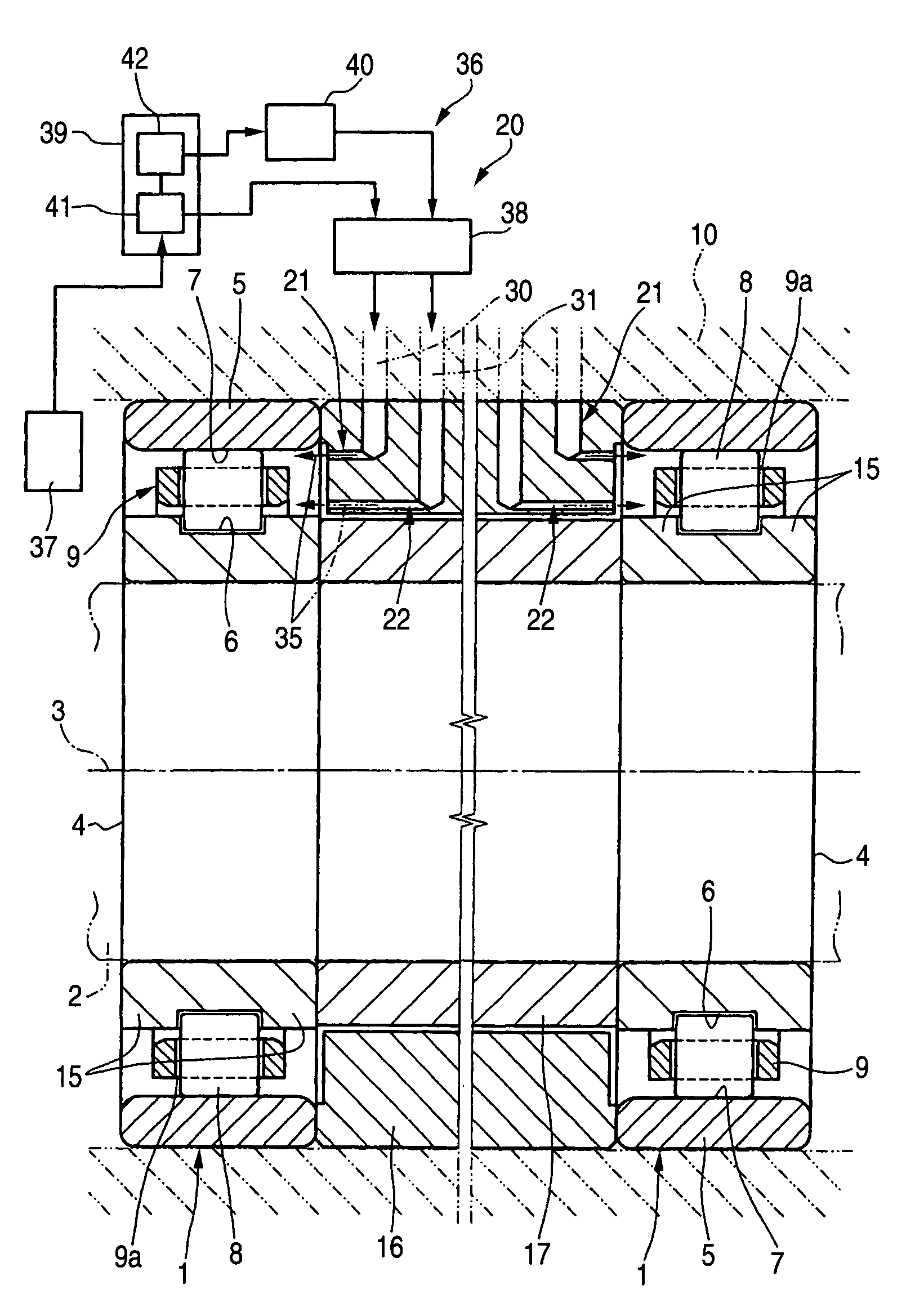
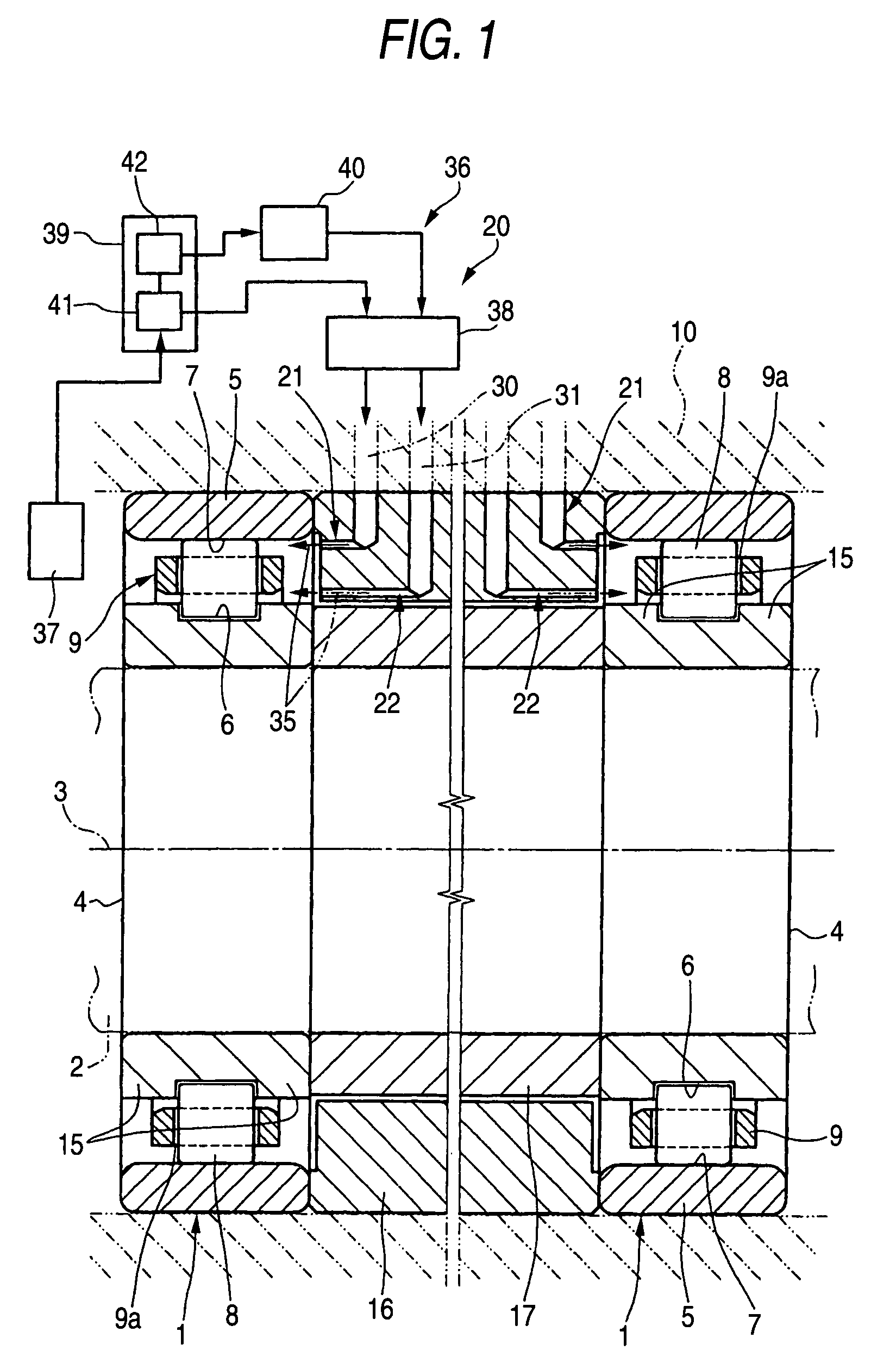
[0028]The first embodiment of the present invention will be explained below. FIG. 1 is a partially sectional view showing a portion of the machine tool in which a roller bearing according to the first embodiment of the present invention is used. FIG. 2 is an enlarged sectional view showing a primary portion of FIG. 1.

[0029]The roller bearing 1 of this embodiment is a cylindrical roller bearing. In this embodiment, a pair of cylindrical roller bearings 1 are arranged on opposite sides in the axial direction of the drive shaft 2 of the machine tool so that the drive shaft 2 can be rotatably supported. The structure of the bearing on one side is the same as the structure of the bearing on the other side. Therefore, the bearing 1 on one side is shown in FIG. 2.

[0030]As shown in FIG. 1, the roller bearing 1 includes: an inner ring member 4, into which the drive shaft 2 is press-fitted, and which is supported rotatably about the axis 3; an outer ring member 5 arranged concentrically with ...

second embodiment

[0047]Next, referring to the sectional view of FIG. 3 and the enlarged sectional view of FIG. 4, the second embodiment according to the present invention will be explained below. The roller bearing of the second embodiment of the present invention includes: an outer ring member 5; an inner ring member 4; a plurality of cylindrical rollers 8; and a cage 9. The structure of the inner ring member 4 is the same as that of the first embodiment. Therefore, same reference marks are used to indicate like parts, and the explanations are omitted here.

[0048]The cage 9 has annular portions 9b to be guided which are protruded outside in the radial direction and arranged on opposite sides of the pockets 9a in the axial direction. This cage 9 is an outer ring guide cage in which the outer circumferential faces 9c of the portions 9b are guided by the inner circumferential face of the outer ring member 5.

[0049]Next, the lubricating device 20 will be explained below. The lubricating device 20 include...

third embodiment

[0059]Next, referring to FIGS. 5 and 6, the third embodiment of the present invention will be explained below. Different points of the roller bearing device of the third embodiment of the present invention from those of the roller bearing of the second embodiment are explained as follows.

[0060]The roller bearing 1 of the roller bearing device of the third embodiment includes shoulder portions 55, the diameter of the inner circumferential face of which is smaller than the diameter of the outer ring raceway surface 7, and which is provided on opposite sides of the outer ring raceway surface 7 of the outer ring member 5. The lubricating device 20 includes a pair of lubricant supply path 56, which are arranged at the boundary portions between the outer ring raceway 7 and the shoulder portions 55, from which the lubricating oil 35 is discharged toward the outer ring raceway surface 7. In each lubricant supply path 56, the supply path 57 provided in the housing 10 is formed. These supply ...


PUM

PropertyMeasurementUnit
speedaaaaaaaaaa
rotating speedaaaaaaaaaa
rotation speedaaaaaaaaaa

Abstract

A bearing device includes: an inner ring member through which a shaft is passed and which is supported rotatably about an axis of the shaft and includes an inner ring raceway surface; an outer ring member arranged concentrically with the inner ring member and including an outer ring raceway surface; a plurality of rollers arranged rollably between the inner ring raceway surface and the outer ring raceway surface; a lubricating path through which lubricant is supplied to at least one of the inner ring raceway surface and the outer ring raceway surface; and a lubricating device which supplies the lubricant to the lubricating path according to rotating speed of the inner ring member about the axis.

Description

BACKGROUND OF THE INVENTION[0001]The present invention relates to a roller bearing device, for example, used for a main shaft of a machine tool. The present invention also relates to a method of lubricating the roller bearing.[0002]A tapered roller bearing device is known in which the generation of heat, which is made in the bearing when the bearing is rotated at high speed, is reduced. The tapered roller bearing device is disclosed in Patent Document 1 for example.[0003]This tapered roller bearing device includes a hole penetrating the inner ring member in the axial direction and a hole penetrating the inner ring member from the hole in the radial direction. This hole is used as an oil supplying hole. A first nozzle from which pressured oil is injected is provided in the outer ring spacer while the first nozzle is opposed to an opening of the oil supplying hole. A through-hole penetrating the inner ring spacer in the axial direction is arranged in the circumferential direction alte...

Claims


Application Information

Patent Timeline
Patent Type & Authority Patents(United States)
IPC IPC(8): F16C19/00F16C19/26F16N31/00F16C19/28F16C33/58F16C33/66F16C35/06F16C37/00G01P3/44
CPCF16C19/26F16C19/54F16C33/6659G01P3/443F16C37/007Y10T29/49771F16N2210/14Y10T29/49702F16C41/007
Inventor SHIMOMURA, TOSHIAKI
Owner JTEKT CORP
Why Eureka
Try Eureka