Wedged profile plate

a profile plate and profile technology, applied in the field of new bone plates, can solve the problems of increasing the possibility of intra-articular protrusion of screws, preventing the perfect orientation of drills and screwdrivers, and always a danger of coracoid process breakage,

Active Publication Date: 2009-12-24
ARTHREX
View PDF7 Cites 31 Cited by
  • Summary
  • Abstract
  • Description
  • Claims
  • Application Information

AI Technical Summary

Benefits of technology

[0009]The present invention provides a bone plate used in conjunction with various procedures to correct certain deformities (including a Latarjet procedure). The bone plate is provided with a plurality of spikes having a truncated, pyramidal shape with a plurality of sides or faces that converge to a tip line. The spikes allow the plate to stay in the right position by simply pressing the plate with the fingers or using a specific instrument on the bone (before the fixation holes are drilled and before the fixation devices such as screws are secured). The bone plate may be provided with side, lateral faces, at least one of them having a non-uniform width (i.e., a wedged profile) to allow for orthograde placement of the fixation device (for example, a screw) even in the case of angled bone surfaces.

Problems solved by technology

Although the Latarjet procedure has been constantly improved since 1954, there remains always a danger that the coracoid process may break apart as a result of various factors such as: (i) the screws being screwed too tightly during the procedure; and / or (ii) medial necrosis of the bone graft due to altered bone-to-bone integration, caused by insufficient mechanical compression, already present in the bone fixation phase.
The coracoid breakage (i.e., medial necrosis of the bone graft) is explained by the intrinsic difficulty of the Latarj et technique, which entails the fixation of the coracoid on the “steep” neck of the scapula.
To obtain a valid match between coracoid and glenoid, the two lag screws must be introduced perpendicular to the neck of the scapula; this step is sometimes made difficult by the small and deep surgical approach, thereby preventing perfect orientation of drill and screwdriver, and increasing anyway the possibility of intra-articular protrusion of the screws.

Method used


Image

  • Wedged profile plate
  • Wedged profile plate
  • Wedged profile plate

Examples


first embodiment

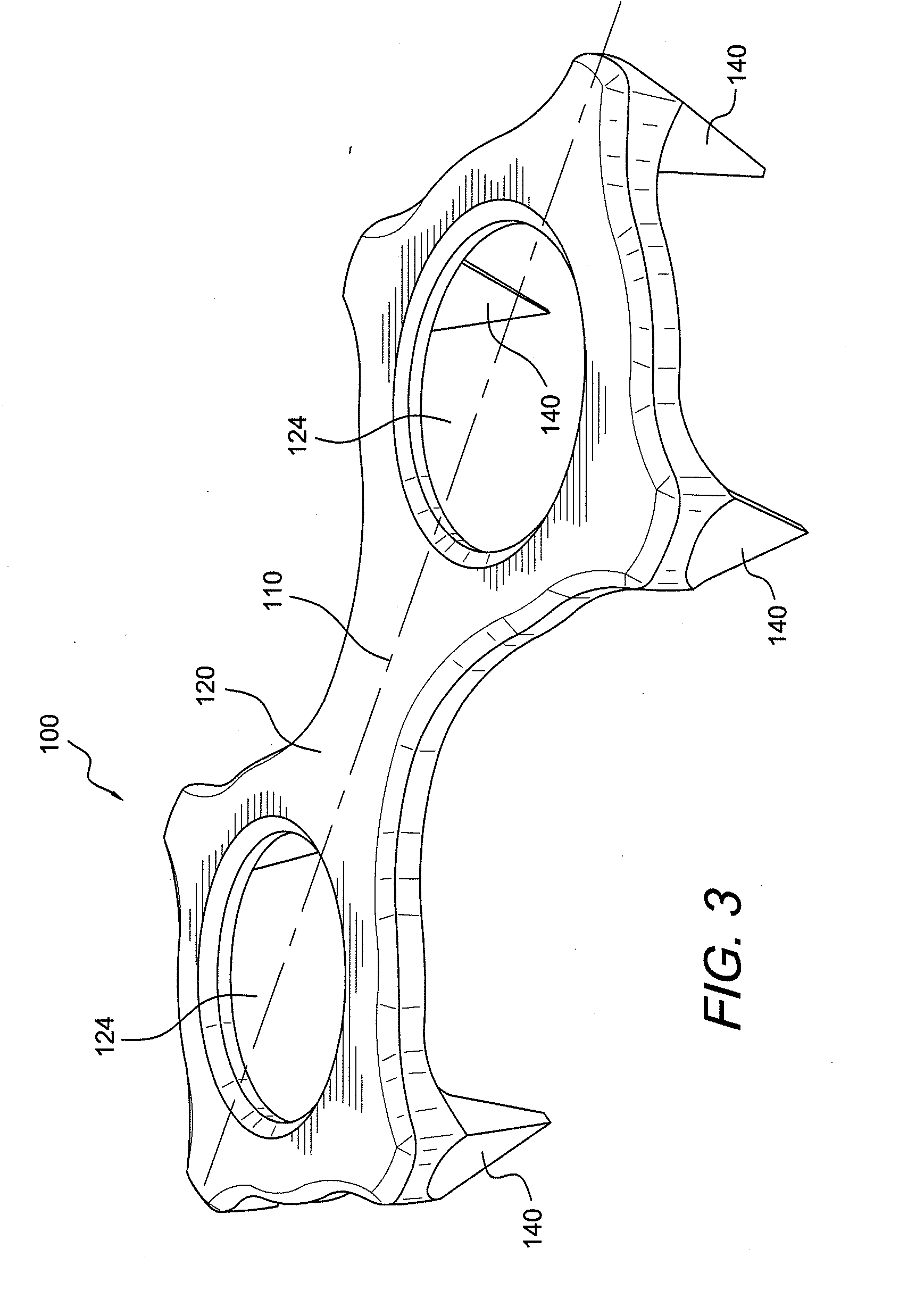
[0020]Bone plate 100 of the present invention (shown in FIGS. 3-5) includes a rigid plate body 120 having an elongated “FIG. 8” configuration, as shown in FIG. 3, for example. As illustrated in FIG. 5a, and according to an exemplary embodiment of the invention, rigid body 120 has a length “L” of about 15 to 20 mm, more preferably of about 18 mm, and a width “W” of about 5 to about 10 mm, more preferably of about 6.5 mm.

[0021]Bone plate 100 is also provided with a plurality of small projecting teeth, protuberances or spikes 140. Projecting teeth or spikes 140 are designed to allow the plate 100 to stay in the right position (once the surgeon has pressed the plate with his / her fingers, or using a specific instrument, on the bone block) before the fixation holes are drilled and before the fixation devices (for example, screws) are secured. The exemplary embodiment illustrated in FIGS. 3-5 shows bone plate 100 provided with six spikes 140, two of the spikes being positioned on the longi...
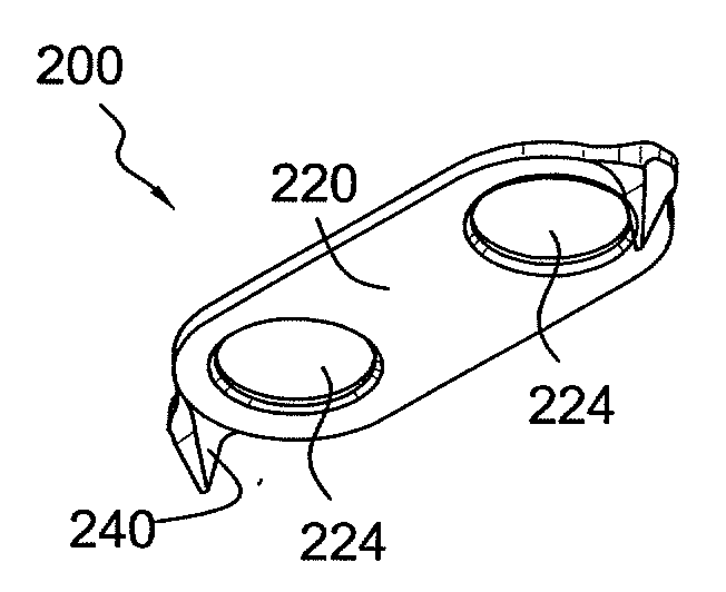
second embodiment

[0024]Bone plate 200 of the present invention (shown in FIGS. 6-8) includes a rigid plate body 220 having an oval shape and provided with a plurality of small projecting teeth, protuberances or spikes 240 (two shown in FIGS. 6-8). Spikes 240 are similar to spikes 140 of plate 100 in that spikes 240 are also provided with a truncated, pyramidal shape, each spike terminating in tip 250 having a length “l” (FIG. 8b) of about 0.1 to 0.2 mm. The height “H” of each spike is of about 3 mm with the bone plate (FIG. 8b) or of about 2.5 mm (without the bone plate).

[0025]Body plate 220 is also provided with two openings 224 (that may be threaded and / or countersunk) configured to receive fixation devices (such as, for example, two fixation devices used for the Latarjet procedure). Projecting teeth or spikes 240 are designed to allow the plate 200 to stay in the right position (once the surgeon has pressed the plate with his / her fingers, or using a specific instrument, on the bone block) before ...

third embodiment

[0027]Bone plate 300 of the present invention (shown in FIG. 9) has a wedged design (as opposed to the parallel design of FIG. 6, for example). The special profile of the plate 300 enables orthograde placement of the fixation device (for example, a screw) even in the case of angled bone surfaces.

[0028]As shown in FIG. 9, bone plate 300 is provided with a rigid body 320 and four spikes 340 provided symmetrically relative to a longitudinal axis 310 of body 320. Spikes 340 are rigid and, according to an exemplary embodiment only, are provided integral with the body 320. Spikes 340 have a truncated, pyramidal shape with a plurality of sides or faces 341 that converge to tip 345 (line 345) of each spike 340. In an exemplary embodiment only, at least one of the spikes has four lateral faces 341 that converge to tip 345. In a preferred embodiment, all spikes have four lateral faces 341 that converge to tip 345. Tip 345 is preferably a thin line with a length “l” of about 0.1 to 0.2 mm. The...


PUM


Abstract

A bone plate used in conjunction with various procedures to correct certain deformities, such as a Latarjet procedure. The bone plate is provided with a plurality of spikes having a truncated, pyramidal shape with a plurality of sides or faces that converge to a tip line. The height of each spike is of about 2.5 to about 3 mm. The design of the spikes allows the plate to stay in the right position by simply pressing the plate with the fingers on the bone or using a specific instrument (before the fixation holes are drilled and the fixation devices such as screws are secured). The bone plate may be provided with side, lateral faces that have a non-uniform width (i.e., a wedged profile) to allow for orthograde placement of the fixation device, even in the case of angled bone surfaces.

Description

CROSS-REFERENCE TO RELATED APPLICATIONS[0001]This application claims the benefit of U.S. Provisional Application No. 61 / 167,808, filed Apr. 8, 2009, and of U.S. Provisional Application No. 61 / 074,528, filed Jun. 20, 2008, the entire disclosures of both of which are incorporated by reference herein.BACKGROUND OF THE INVENTION[0002]1. Field of the Invention[0003]The present invention relates to a novel bone plate.[0004]2. Description of the Related Art[0005]Osteotomies are procedures that surgically reorient the alignment of a deformed bone. The aim of an osteotomy is to realign the bearing surfaces of a joint to allow normal areas to articulate, moving abnormal areas away from the load-bearing axis.[0006]The Latarjet procedure is known in the art and describes the coracoid bone block procedure. French surgeon Michel Latarjet first suggested that the horizontal limb of the coracoid process be fixed with a screw flush to the anteroinferior margin of the glenoid, making a horizontal inc...

Claims


Application Information

Patent Timeline
Patent Type & Authority Applications(United States)
IPC IPC(8): A61B17/80A61F5/00
CPCA61B17/8061A61B17/8095A61B17/809
Inventor DI GIACOMO, GIOVANNICONSTANTINI, ALBERTO
Owner ARTHREX
Why Eureka
Try Eureka