Image forming apparatus and image forming method
- Summary
- Abstract
- Description
- Claims
- Application Information
AI Technical Summary
Benefits of technology
Problems solved by technology
Method used
Image
Examples
first embodiment
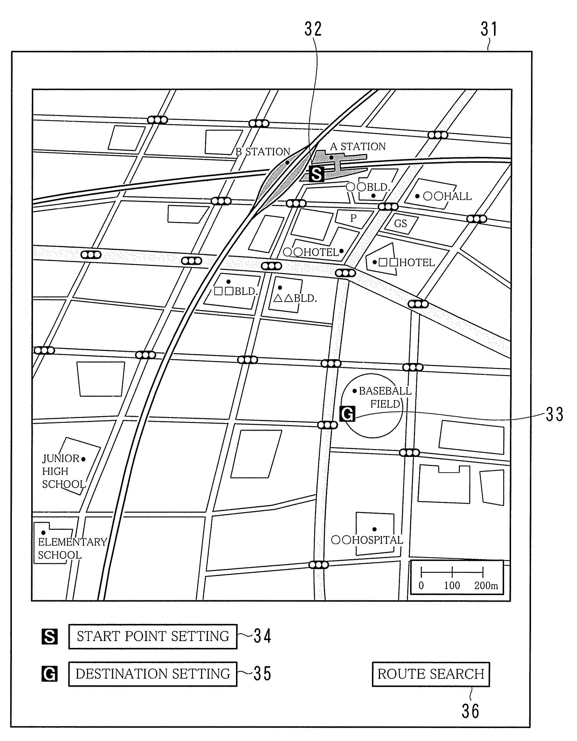
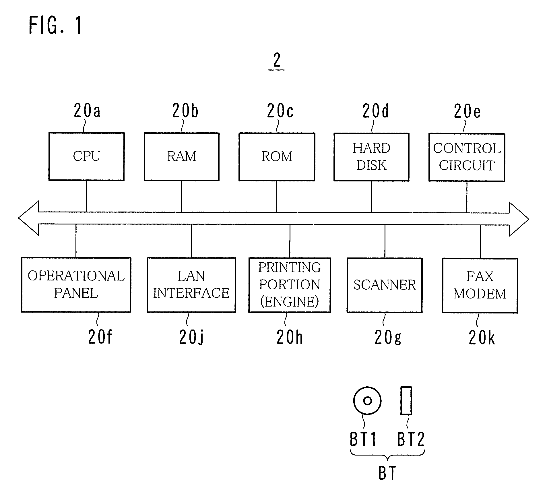
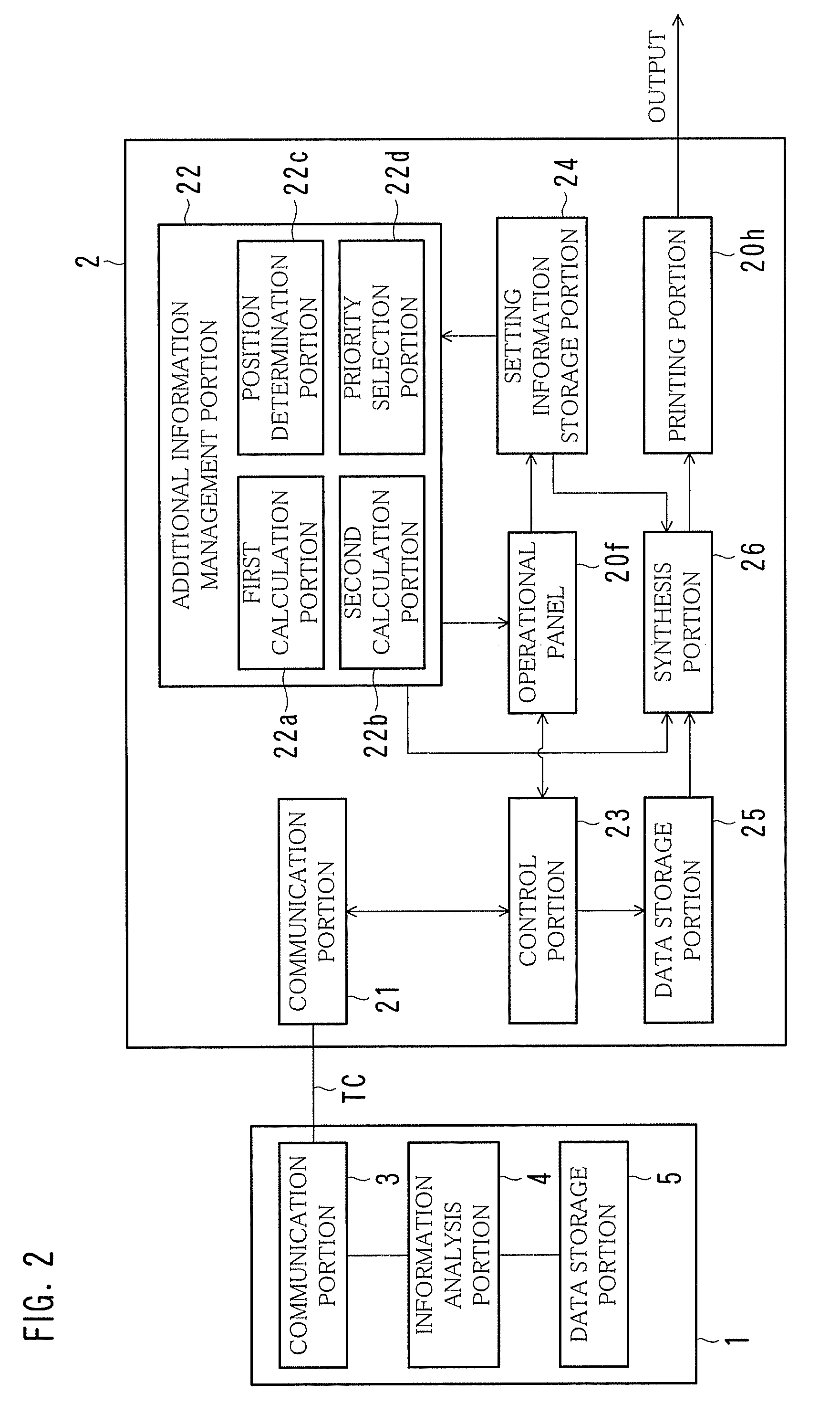
[0029]FIG. 1 is a diagram illustrating an example of the hardware configuration of an image forming apparatus 2; FIG. 2 is a diagram illustrating an example of the functional configuration of the image forming apparatus 2; FIG. 3 is a sequence diagram illustrating an example of events between the image forming apparatus 2 and a sever 1; FIG. 4 is a diagram illustrating an example of a screen used when route search is performed; FIG. 5 is a diagram illustrating an example of a screen showing a route search result; FIGS. 6 and 7 are diagrams illustrating examples of a display portion 31 of an operational panel 20f; FIG. 8 is a diagram illustrating an example of an algorithm for depicting a synthesis method for an image included in additional information; FIG. 9 is a diagram illustrating an example of a screen used for selecting additional information; and FIG. 10 is a diagram illustrating an example of a screen in which images included in additional information are incorporated.
[0030]...
second embodiment
[0078]FIG. 13 is a diagram illustrating an example of a screen used when a priority of additional information to be added is set; and FIG. 14 is a flowchart illustrating another example of the flow of a map additional information printing process.
[0079]In the first embodiment, a user selects additional information. Instead, in the second embodiment, a priority selection portion 22d (see FIG. 2) automatically selects additional information based on a priority for each facility, located along the route, that has been set in advance by a user.
[0080]When a user presses the priority setting button 45 (see FIG. 7), as illustrated in FIG. 13, a drop-down priority selection button 53 appears on the display portion 31. The user can use the drop-down priority selection button 53 to designate a priority based on which additional information is added. For example, the user can designate, as a first priority, information on intersections along a route from a start point to a destination, and des...
third embodiment
[0085]FIG. 15 is a flowchart illustrating yet another example of the flow of a map additional information printing process.
[0086]In the first embodiment, the number of images included in additional information that can be added is calculated based on an additional area size and an additional image size that are set by a user. In the third embodiment, a user sets an additional area size and the number of images included in additional information, and a second calculation portion 22b (see FIG. 2) calculates a unit additional image size corresponding to the size of a single image included in the additional information based on the additional area size and the number of images included in the additional information that are set by the user. If the unit additional image size thus calculated is equal to or lower than a preset lower limit value, then an image included in the additional information is enlarged and printed onto a separate sheet of paper without incorporating such an image in...
PUM
 Abstract
Description
Claims
Application Information
 - R&D
- Intellectual Property
- Life Sciences
- Materials
- Tech Scout
- Unparalleled Data Quality
- Higher Quality Content
- 60% Fewer Hallucinations
Browse by: Latest US Patents, China's latest patents, Technical Efficacy Thesaurus, Application Domain, Technology Topic, Popular Technical Reports.
© 2025 PatSnap. All rights reserved.Legal|Privacy policy|Modern Slavery Act Transparency Statement|Sitemap|About US| Contact US: help@patsnap.com


