Image forming apparatus and image forming method

a technology of image forming and forming methods, applied in the direction of surveying, navigation, instruments, etc., can solve the problems of inconvenient user travel to a destination with a plurality of printed materials, waste of paper resources, and difficulty in knowing which part of the entire map is an area of the enlarged map, so as to reduce unnecessary waste of paper resources

Inactive Publication Date: 2012-07-24
KONICA MINOLTA BUSINESS TECH INC
View PDF18 Cites 4 Cited by
  • Summary
  • Abstract
  • Description
  • Claims
  • Application Information

AI Technical Summary

Benefits of technology

[0012]The present disclosure is directed to solve the problems pointed out above, and therefore, an object of an embodiment of the present invention is to reduce unnecessary waste of paper resources and to provide a printed material corresponding to an easy-to-use map as compared to conventional apparatuses / methods.

Problems solved by technology

In the conventional method described above, however, the entire map is printed onto a sheet of paper and an image corresponding to an enlarged map desired by a user is printed onto a separate sheet of paper, thereby resulting in the waste of paper resources.
Further, it is inconvenient for the user to go to a destination with a plurality of printed materials, and it is also burdensome for the user to find a necessary map from among the plurality of printed materials.
Moreover, it is difficult to know which part of the entire map an area of the enlarged map printed on the separate sheet of paper corresponds to.

Method used


Image

  • Image forming apparatus and image forming method
  • Image forming apparatus and image forming method
  • Image forming apparatus and image forming method

Examples


first embodiment

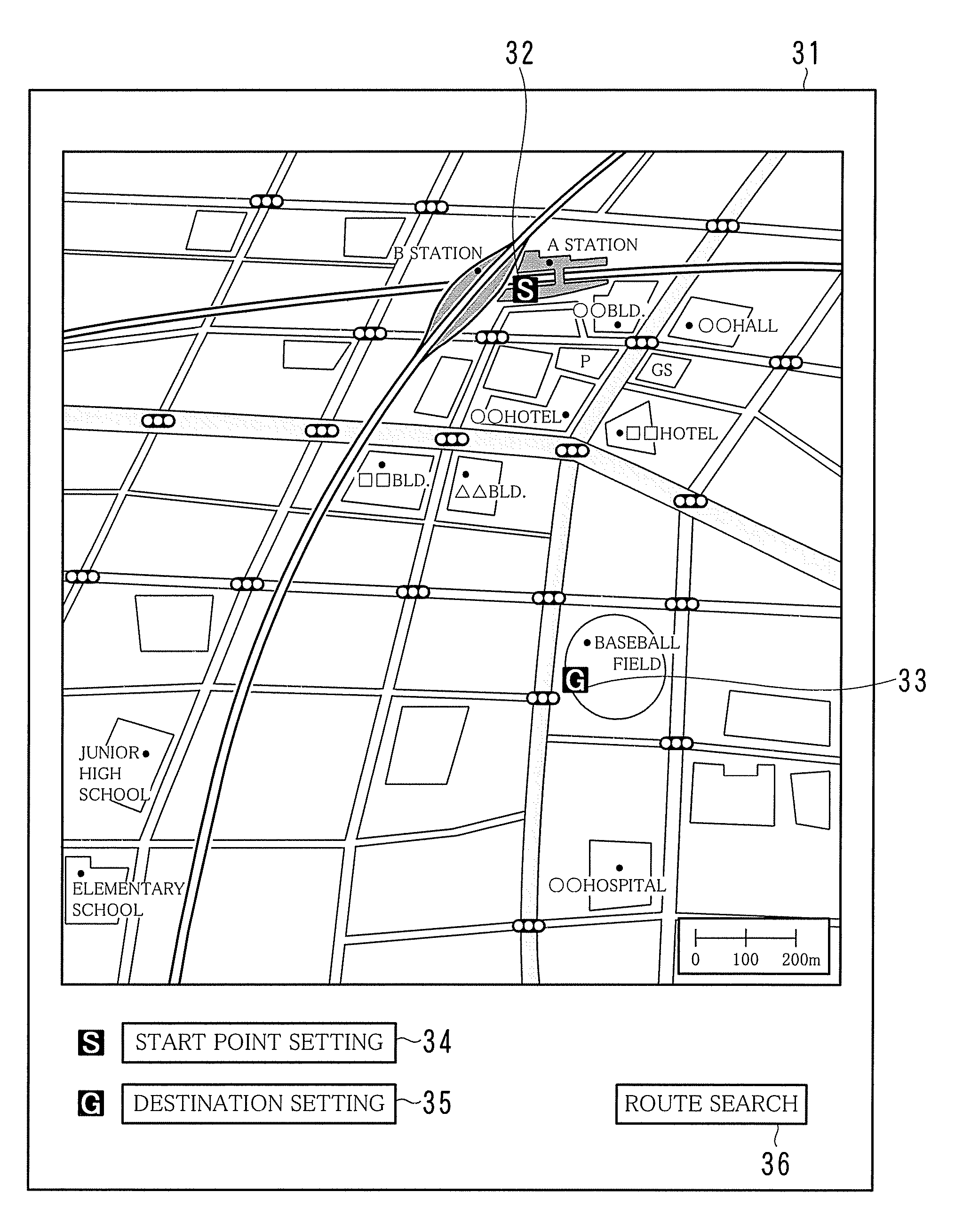
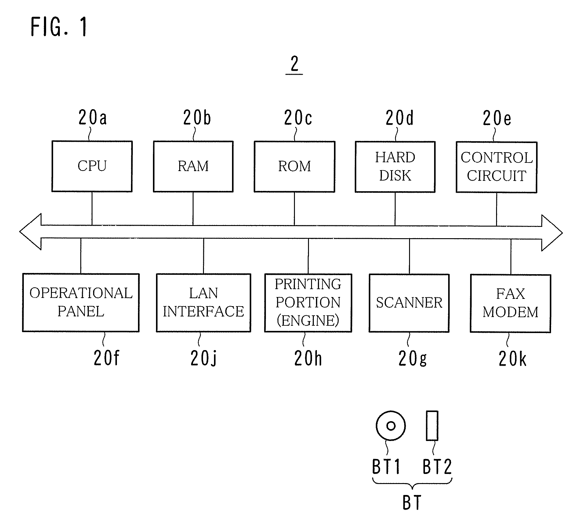
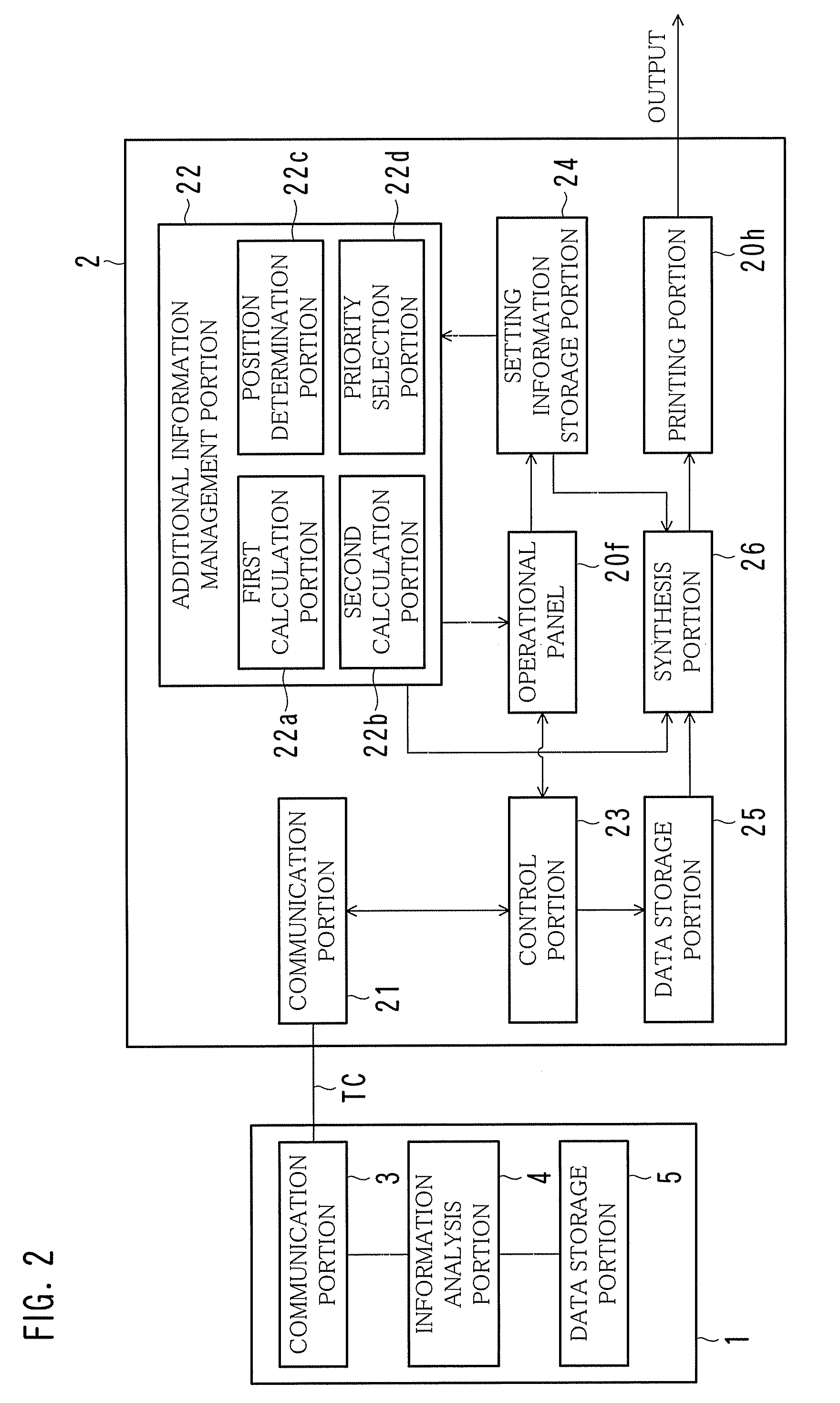
[0029]FIG. 1 is a diagram illustrating an example of the hardware configuration of an image forming apparatus 2; FIG. 2 is a diagram illustrating an example of the functional configuration of the image forming apparatus 2; FIG. 3 is a sequence diagram illustrating an example of events between the image forming apparatus 2 and a sever 1; FIG. 4 is a diagram illustrating an example of a screen used when route search is performed; FIG. 5 is a diagram illustrating an example of a screen showing a route search result; FIGS. 6 and 7 are diagrams illustrating examples of a display portion 31 of an operational panel 20f; FIG. 8 is a diagram illustrating an example of an algorithm for depicting a synthesis method for an image included in additional information; FIG. 9 is a diagram illustrating an example of a screen used for selecting additional information; and FIG. 10 is a diagram illustrating an example of a screen in which images included in additional information are incorporated.

[0030]...

second embodiment

[0078]FIG. 13 is a diagram illustrating an example of a screen used when a priority of additional information to be added is set; and FIG. 14 is a flowchart illustrating another example of the flow of a map additional information printing process.

[0079]In the first embodiment, a user selects additional information. Instead, in the second embodiment, a priority selection portion 22d (see FIG. 2) automatically selects additional information based on a priority for each facility, located along the route, that has been set in advance by a user.

[0080]When a user presses the priority setting button 45 (see FIG. 7), as illustrated in FIG. 13, a drop-down priority selection button 53 appears on the display portion 31. The user can use the drop-down priority selection button 53 to designate a priority based on which additional information is added. For example, the user can designate, as a first priority, information on intersections along a route from a start point to a destination, and des...

third embodiment

[0085]FIG. 15 is a flowchart illustrating yet another example of the flow of a map additional information printing process.

[0086]In the first embodiment, the number of images included in additional information that can be added is calculated based on an additional area size and an additional image size that are set by a user. In the third embodiment, a user sets an additional area size and the number of images included in additional information, and a second calculation portion 22b (see FIG. 2) calculates a unit additional image size corresponding to the size of a single image included in the additional information based on the additional area size and the number of images included in the additional information that are set by the user. If the unit additional image size thus calculated is equal to or lower than a preset lower limit value, then an image included in the additional information is enlarged and printed onto a separate sheet of paper without incorporating such an image in...


PUM


Abstract

An image forming apparatus is provided with a first communication portion that obtains route information from a server, a second communication portion that obtains, from the server, additional information relating to the route information, a synthesis portion that incorporates an image included in the additional information into an area that is contained in an image included in the route information and that excludes the route and generates composite information, and a printer that prints an image based on the composite information generated by the synthesis portion onto a recording medium.

Description

[0001]This application is based on Japanese Patent Application No. 2008-159505 filed on Jun. 18, 2008, the contents of which are hereby incorporated by reference.BACKGROUND OF THE INVENTION[0002]1. Field of the Invention[0003]The present invention relates to an image forming apparatus such as an MFP, and an image forming method.[0004]2. Description of the Related Art[0005]Image forming apparatuses performing an image forming process have conventionally been used in offices of business, convenience stores, or various places of other kinds. Such image forming apparatuses are, for example, copiers, printers, facsimile machines, and multifunction devices called combination machines or Multi-Function Peripherals (MFPs).[0006]In parallel with the improvement of the performance of image forming apparatuses, additional features thereof are continuously being developed. A variety of additional features of image forming apparatuses have already been developed.[0007]For example, an image formi...

Claims


Application Information

Patent Timeline
Patent Type & Authority Patents(United States)
IPC IPC(8): G01C21/00
CPCB41J3/46G01C21/00
Inventor SUGIMOTO, HIROAKI
Owner KONICA MINOLTA BUSINESS TECH INC
Why Eureka
Try Eureka