Suction head for vacuum cleaner

a vacuum cleaner and suction head technology, applied in the direction of vacuum cleaners, cleaning equipment, domestic applications, etc., can solve the problems of deteriorating cleaning efficiency, dust and foreign matter on the floor cannot be easily suctioned into the suction head, etc., and achieve the effect of efficient suctioning dus

Inactive Publication Date: 2009-12-31
WOONGJIN COWAY
View PDF2 Cites 11 Cited by
  • Summary
  • Abstract
  • Description
  • Claims
  • Application Information

AI Technical Summary

Benefits of technology

[0012]The present invention is conceived to solve the above and other problems of the related art, and an aspect of the present invention is to provide a suction h...

Problems solved by technology

In the conventional vacuum cleaner, when the suction head is moved backward, a path of suctioning dust and foreign matter on the floor to the intake port of the sucti...

Method used


Image

  • Suction head for vacuum cleaner
  • Suction head for vacuum cleaner
  • Suction head for vacuum cleaner

Examples


Embodiment Construction

[0031]Hereinafter, one exemplary embodiment of the present invention will be described in detail with reference to the accompanying drawings. It should be noted that the drawings are not to precise scale and may be exaggerated in thickness of lines or sizes of components for descriptive convenience and clarity only. Furthermore, the terms as used herein are defined by taking functions of the present invention into account and can be changed according to the custom or intention of users or operators. Therefore, definition of the terms should be made according to the entirety of the disclosure set forth herein.

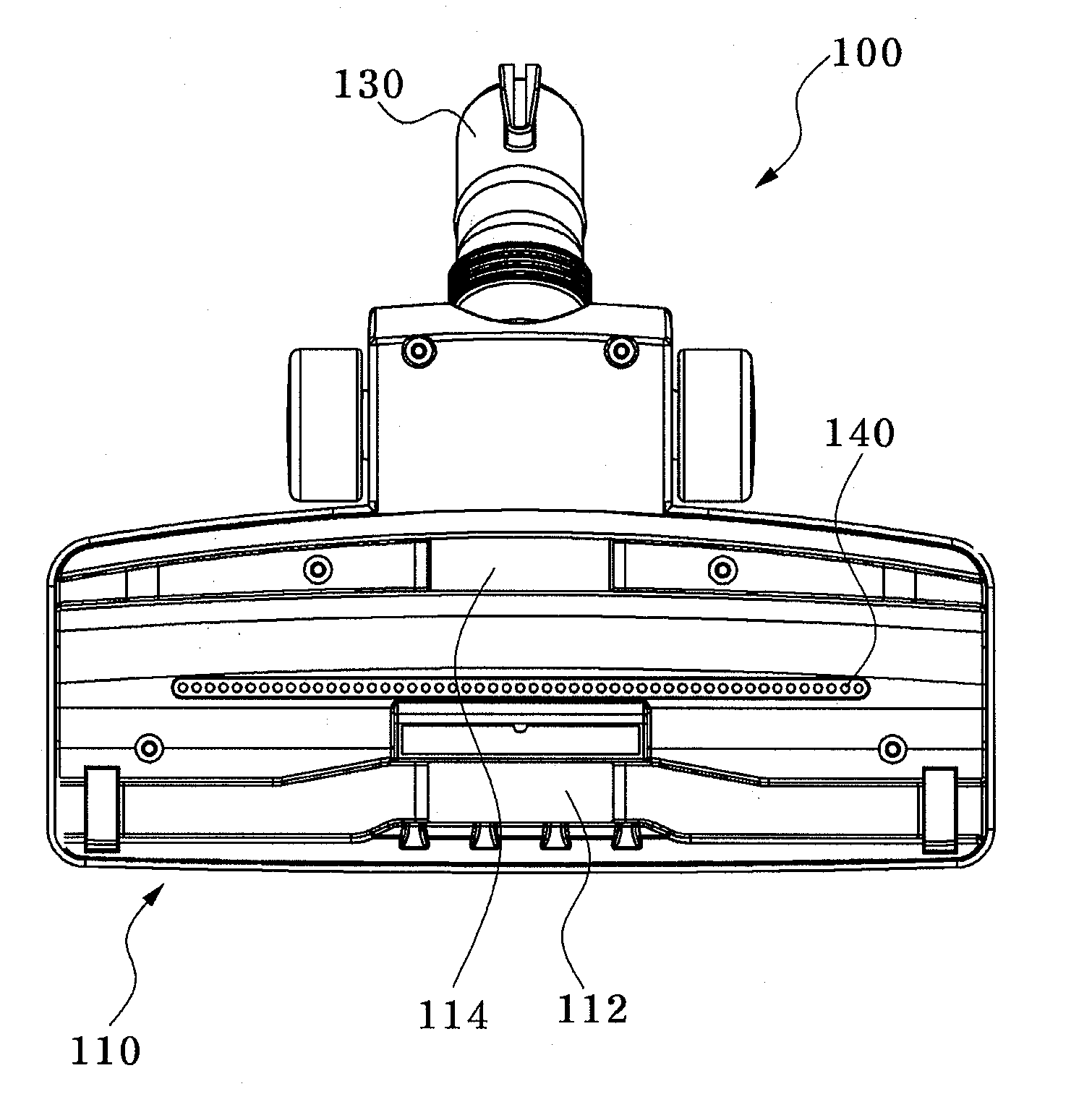
[0032]FIG. 3 is a perspective view of a suction head according to one embodiment of the present invention, FIG. 4 is a bottom view of the suction head of FIG. 3, and FIG. 5 is a side section view of the suction head taken along line A-A of FIG. 3.

[0033]Referring to FIGS. 3 to 5, a suction head 100 for vacuum cleaners according to one embodiment of the present invention includes ...


PUM


Abstract

Disclosed herein is a suction head for vacuum cleaners. The suction head includes a housing constituting an outer appearance of the suction head, a plurality of intake ports formed in a lower surface of the housing, and a sweeper disposed between the intake ports.

Description

CROSS-REFERENCE TO RELATED APPLICATIONS[0001]The present application claims priority to Korean patent application number 10-2008-0061342, filed on Jun. 27, 2008, which is incorporated by reference in its entirety.BACKGROUND OF THE INVENTION[0002]1. Field of the Invention[0003]The present invention relates to a suction head for vacuum cleaners and, more particularly, to a suction head for vacuum cleaners which can efficiently suction dust or other foreign matter from a floor surface irrespective of forward or backward movement of the suction head.[0004]2. Description of the Related Art[0005]In general, a vacuum cleaner is configured to generate a strong suction force by driving a motor to collect dust or other foreign matter from the floor or the like.[0006]FIG. 1 is a perspective view of a conventional vacuum cleaner and FIG. 2 is a bottom view of a suction head of the conventional vacuum cleaner shown in FIG. 1.[0007]Referring to FIG. 1, the conventional vacuum cleaner includes a b...

Claims


Application Information

Patent Timeline
IPC IPC(8): A47L9/02
CPCA47L9/02A47L9/066A47L9/0653A47L9/00
Inventor LEE, SUNG WHAN
Owner WOONGJIN COWAY
Why Eureka
Try Eureka