Power tool

a technology of power tools and power tools, applied in the field of power tools, can solve the problems of particularly low manufacturing cost, and achieve the effects of improving the efficiency of the pelton turbine, convenient and simple operation of the power tool and/or the vacuum cleaner, and simple and economical manner

Inactive Publication Date: 2006-05-09
ROBERT BOSCH GMBH
View PDF19 Cites 20 Cited by
  • Summary
  • Abstract
  • Description
  • Claims
  • Application Information

AI Technical Summary

Benefits of technology

[0004]The present invention having the features of Claim 1 has the advantage that the power tool—which is operated without its own electric motor and using only the vacuum from a vacuum cleaner, and which is designed as a sanding machine—has a level of efficiency for its applications that is so high that it enables nearly completely dust-free sanding and removal of all dust particles that form during sanding, thereby combining a high degree of abrasive wear with a highly effective suctioning-off of the sanding dust.
[0005]Due to the fact that a Pelton turbine provided with a forward-guiding vane row functions as an alternative drive of the power tool, a particularly low-profile drive with improved performance is realized.
[0006]Due to the fact that forward-guiding and rearward-guiding vane rows are integrated in the housing structure of the power tool, their manufacturing costs are particularly low.

Problems solved by technology

Due to the fact that forward-guiding and rearward-guiding vane rows are integrated in the housing structure of the power tool, their manufacturing costs are particularly low.

Method used


Image

  • Power tool
  • Power tool
  • Power tool

Examples


Embodiment Construction

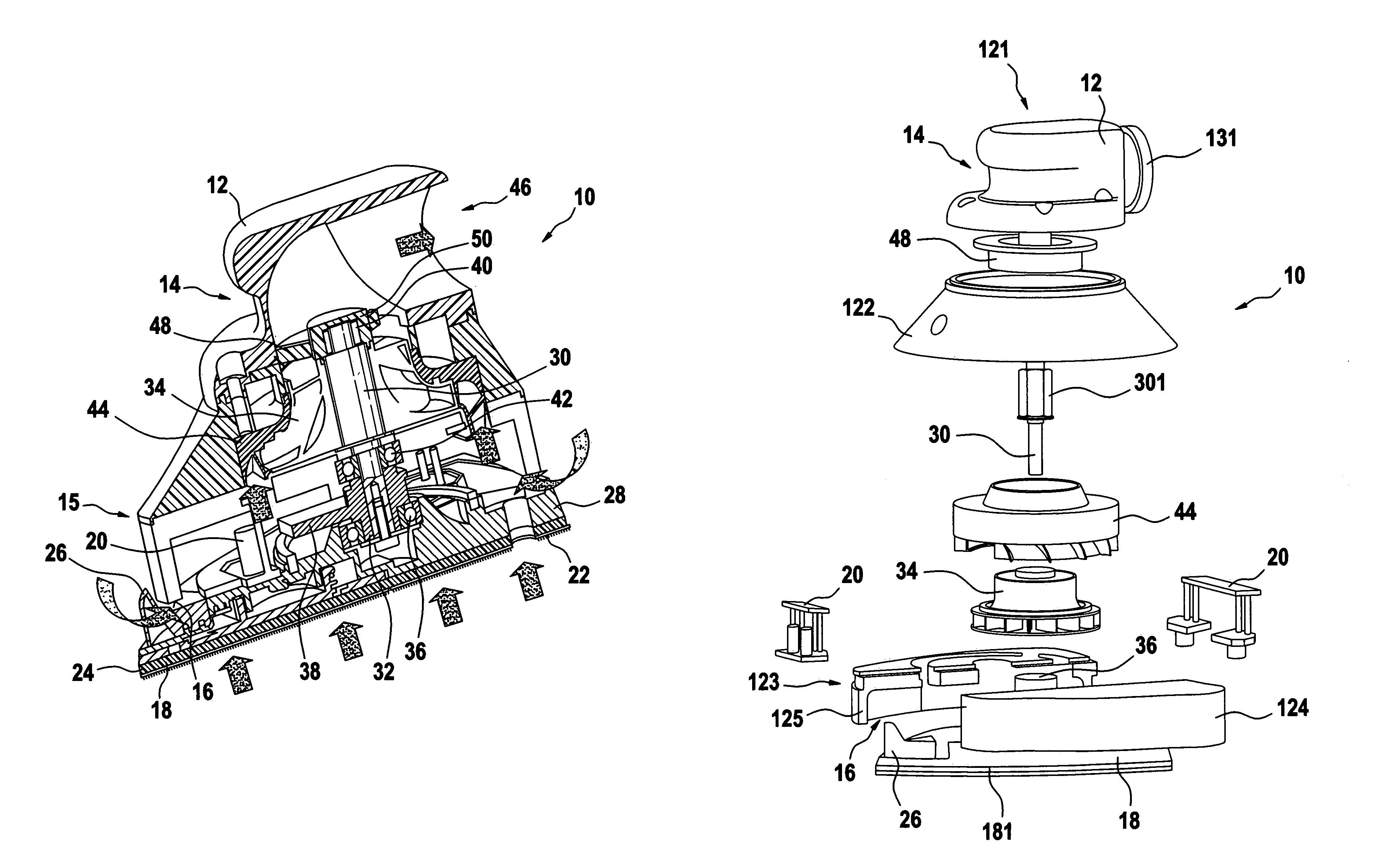
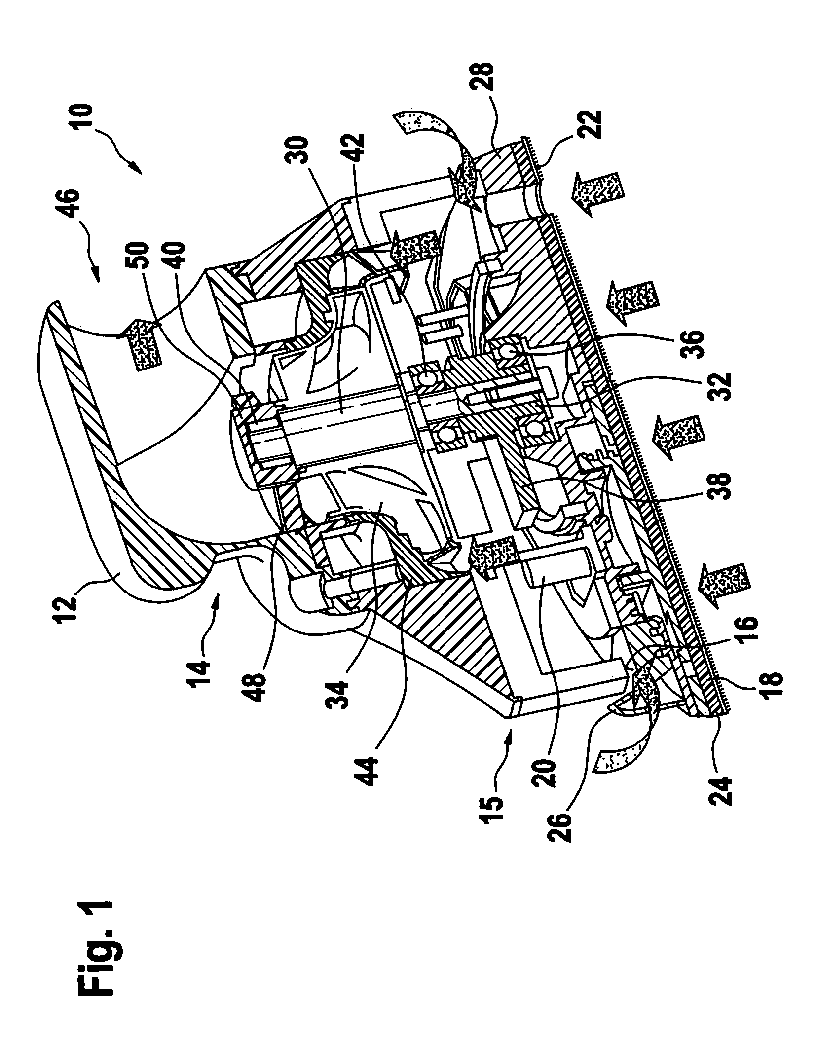
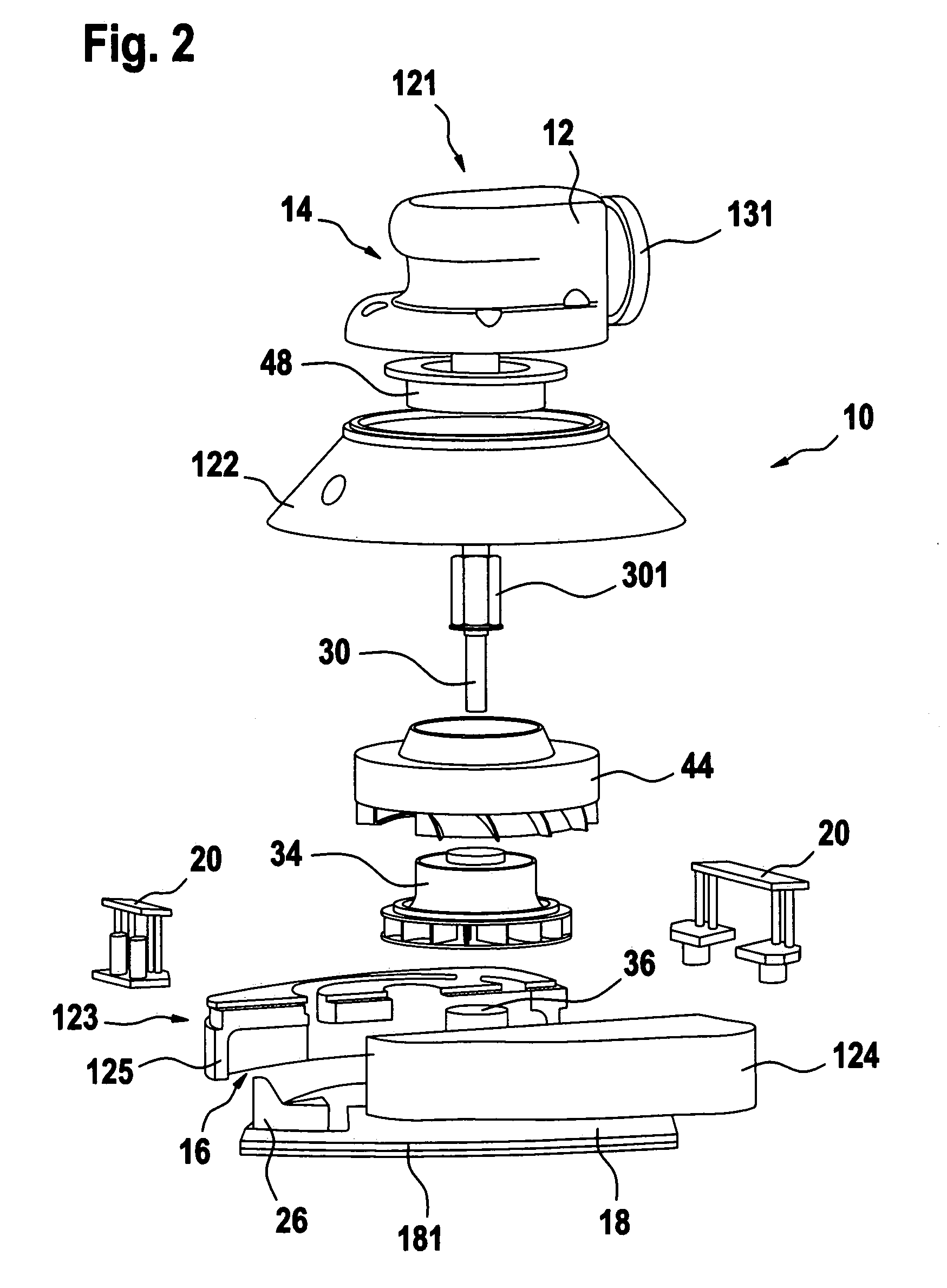
[0023]FIG. 1 shows a power tool 10 designed as an oscillating sander. It is composed of a housing 12 which is configured as a handle in its upper region, the handle continuing downward in a waist-like constriction 14 capable of being encompassed by the operator's fingers, and then widens to form a bell-shaped region 15.

[0024]Housing 12 terminates at the bottom at a flat lower edge 16 which, in its vertical projection downward, forms a triangle with outwardly arched sides. A sanding disk 18 is positioned parallel with lower edge 16, which is elastically joined with housing 12 via elastic oscillating bodies 20.

[0025]Sanding disk 18 extends with its iron-shaped surface outwardly past the triangular, vertically downwardly projecting contour of lower edge 16 and has retaining means on its underside for accommodating a sanding pad 22.

[0026]Sanding disk 18 includes a button 26 on its front, center tip 24. When said button is swiveled to the side, sanding disk 18 can be removed from housing...


PUM


Abstract

A power tool with a housing (12) and a tool (18, 22) located thereon such that it is capable of being driven in a rotating and / or oscillating manner, the tool being operable as directed using vacuum flow, in particular using a vacuum cleaner. The power tool is made particularly powerful by the fact that a radial turbine wheel (34) with forward-guiding and rearward-guiding vane rows (44, 48) functions as the drive.

Description

BACKGROUND OF THE INVENTION[0001]The present invention relates to a power tool according to the definition of the species in Claim 1.[0002]A power tool is known from U.S. Pat. No. 6,347,985 B 1, which is driven solely via the vacuum flow of a vacuum cleaner. The main feature of the known power tool is a customary Pelton turbine which uses the vacuum of the vacuum cleaner to rotate the driven spindle and, therefore, to drive the tool.[0003]The efficiency of the known power tools with axial and Pelton turbines cannot fully meet the high demands for work output and suction performance of these power tools which are capable of being operated with commercially available vacuum cleaners.SUMMARY OF THE INVENTION[0004]The present invention having the features of Claim 1 has the advantage that the power tool—which is operated without its own electric motor and using only the vacuum from a vacuum cleaner, and which is designed as a sanding machine—has a level of efficiency for its application...

Claims


Application Information

Patent Timeline
Patent Type & Authority Patents(United States)
IPC IPC(8): B24B7/18B23Q5/06B24B23/00B24B47/14B24B55/10B24D15/00B25F5/00
CPCB24B23/00B24B55/10B24B47/14B23Q5/06
Inventor HOFFMANN, ERHARDFUCHS, FRANK
Owner ROBERT BOSCH GMBH
Why Eureka
Try Eureka