Clip

a technology of clip and clip rod, which is applied in the field of clips, can solve the problems of long time required for fastening the console box, the deviation of the positional angle relative to the longitudinal direction cannot be absorbed, etc., and achieve the effect of convenient operation

Active Publication Date: 2009-12-31
DAIWA KASEI IND CO LTD +1
View PDF6 Cites 1 Cited by
  • Summary
  • Abstract
  • Description
  • Claims
  • Application Information

AI Technical Summary

Benefits of technology

[0017]Further, the first long hole of the attachment receiving member into which the positioning boss is fitted is formed in a direction at substantially right angle relative to the longitudinal direction of the cutaway groove portion of the pedestal portion. At the same time, the width of the second long hole of the attachment receiving member into which the fitting head portion of the clip is substantially equal to the width of the fitting head portion. Therefore, after the positioning boss is fitted to the first long hole, the movement of the clip in the longitudinal direction of the cutaway groove portion, that is, the positional deviation in the direction orthogonal to the longitudinal direction of the second long hole of the attachment receiving member can be prevented. That is, the positional deviation relative to the attachment member and rattling of the clip due to impact force exerted after the attachment member is attached to the attachment receiving member can be prevented.
[0018]Further, a pair of contact portions extended upward to a predetermined height at substantially right angle from the opposite edge portions of the flat plate portion of the clip in a direction at substantially right angle relative to the longitudinal direction of the cutaway groove portion is brought into contact with the attachment receiving member. At the same time, a pair of elastic locking pieces of the clip is elastically locked with the periphery of each longer side portion of the second long hole of the attachment receiving member. Thus, the attachment receiving member is pinched between the pair of contact portions and the pair of elastic locking pieces, and the clip can be assuredly prevented from rattling.
[0019]Further, according to the clip of the present invention, if the attachment member includes a rib portion provided in an upright posture on the outside of the side surface portion of the upper wall of the pedestal portion, and an extending portion elastically deformable downward and extending substantially vertically from the rib portion at the height opposing to the flange portion up to the inlet portion of the cutaway groove portion, when the flange portion moves while depressing the e...

Problems solved by technology

However, there still remains a problem that the positional deviation in a direction at right angle relative to this longitudinal direction cannot be ab...

Method used


Image

  • Clip
  • Clip
  • Clip

Examples


Embodiment Construction

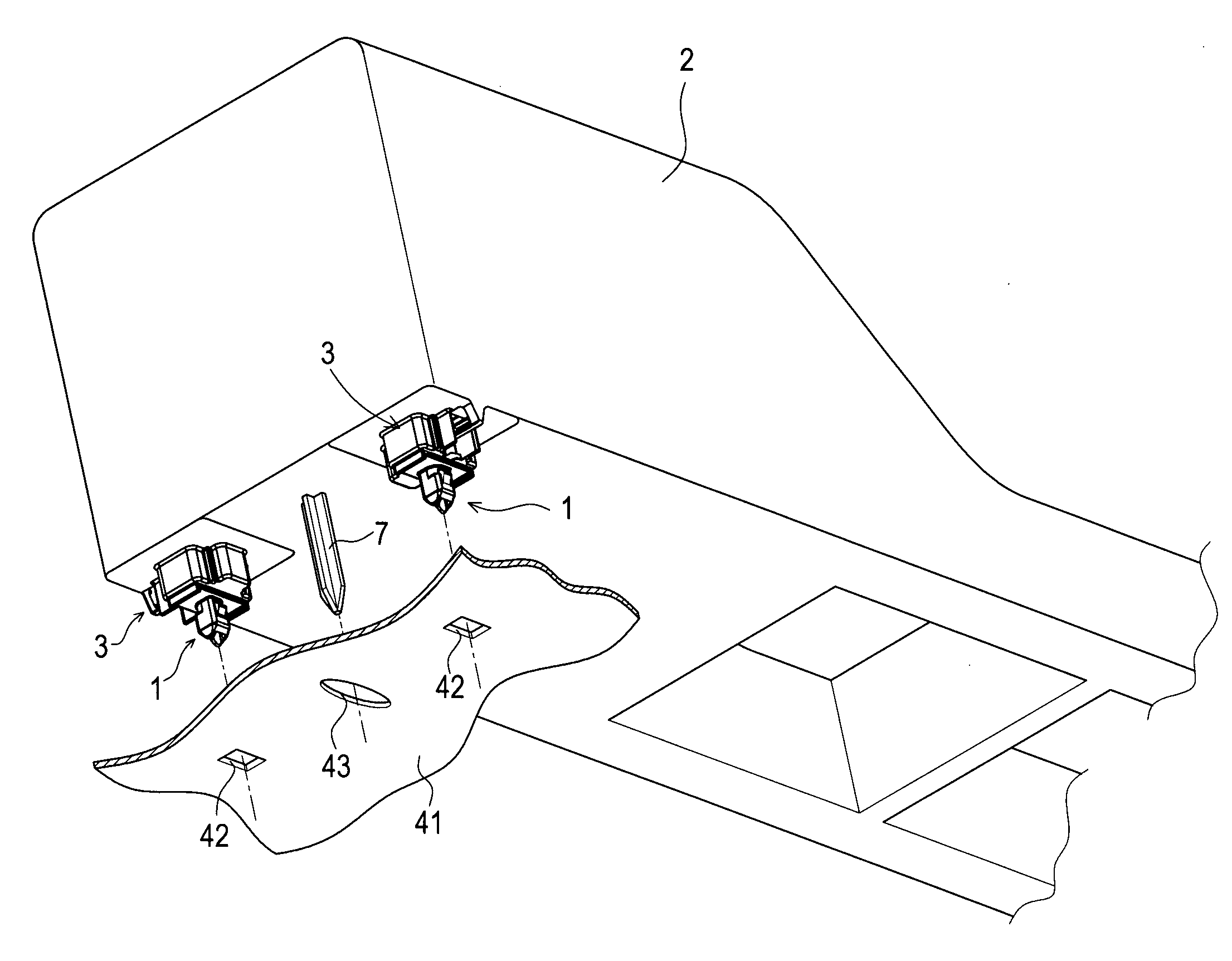
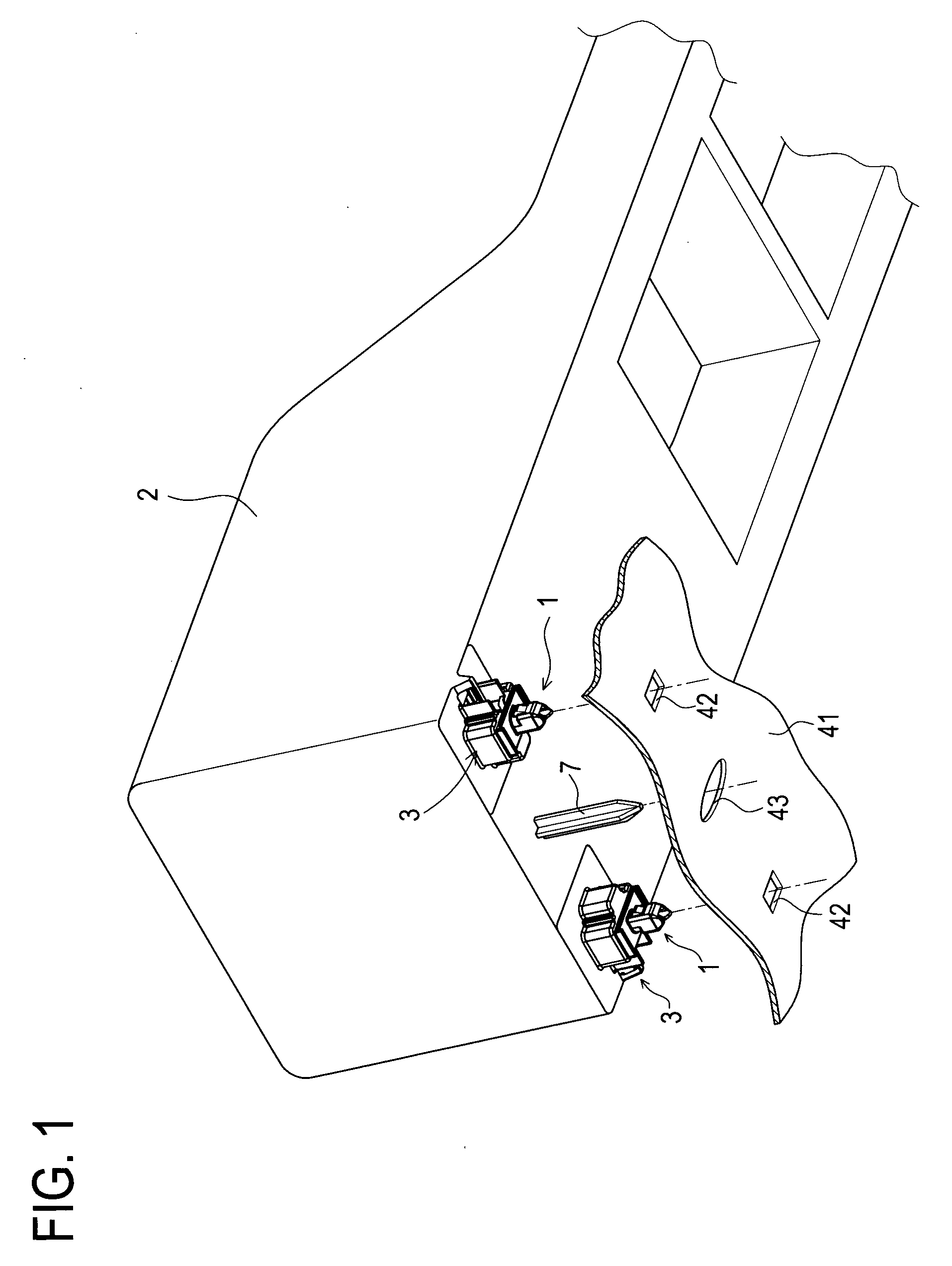
[0081]Hereinafter, a clip according to the present invention will be described in detail with reference to the drawings based on an embodiment which has embodied the present invention. First, an entire structure related to a clip according to this embodiment, an assembling portion of the console box as an attachment member to which the clip is assembled, and each long hole of the attachment receiving member composed of a metal plate (body) to constitute an automobile body with which the clip is locked is described based on FIG. 1.

[0082]FIG. 1 is a perspective view schematically showing a clip according to this embodiment, an assembling portion of a console box to which the clip is assembled, and each long hole of the attachment receiving member with which the clip is locked.

[0083]As shown in FIG. 1, the clip 1 is assembled to each of a pair of assembling portion 3 provided on the left and right corner portions at the front side on the bottom surface portion of the console box 2. On ...


PUM


Abstract

Each clip 1 is fitted into a cutaway groove portion 6 of a pedestal portion 5 of each assembling portion 3 provided on a bottom surface portion of a console box 2. After that, a positioning boss 7 is fitted into a long hole 43 formed in an attachment receiving member 41, and at the same time, a fitting head portion 28 of each clip 1 is fitted into each long hole 42 formed in the attachment receiving member 41. As each fitting head portion 28 is fitted into each long hole 42 formed in the attachment receiving member 41 and a boss portion 22 slides in the cutaway groove portion 6. Each of a pair of elastic locking pieces 31 is elastically locked with the periphery of each longer side portion of each long hole 42.

Description

TECHNICAL FIELD[0001]The present invention relates to a clip for use in attaching an attachment member such as a console box and an instrument panel to an attachment receiving member such as an automobile body. In particular, the present invention relates to a clip that enables attachment and detachment of the attachment member to and from the attachment receiving member in an extremely easy one-touch operation while the clip is always integrally handled with the attachment member to which the clip is assembled.BACKGROUND ART[0002]Conventionally, various kinds of clips have been proposed for use in attaching a console box, instrument panel, and the like to various kinds of panels constituting an automobile body.[0003]For example, there is a console device to be attached on a floor of a vehicle body. In attaching the console device on the floor of the vehicle body, a fitting hole formed on a flange of the console box and a through hole formed on a seat portion are aligned to two fitt...

Claims


Application Information

Patent Timeline
IPC IPC(8): A44B21/00A44B99/00B60R7/04F16B5/06F16B19/00
CPCF16B5/065F16B21/086Y10T24/44017Y10T24/44026Y10T24/30Y10T24/309B60R7/04B60R13/02F16B5/06F16B21/02
Inventor KATOH, MAKOTOKAMIYA, HARUHISASAWADA, SHINICHISHIBATA, MINORUSAKAKIBARA, YASUHIRO
Owner DAIWA KASEI IND CO LTD
Why Eureka
Try Eureka