Device and method for controlling tracking information, and radar device

a tracking information and radar technology, applied in the direction of measuring devices, instruments, using reradiation, etc., can solve the problem of not being able to instantly determine the target displayed by the other radar devi

Active Publication Date: 2012-12-13
FURUNO ELECTRIC CO LTD
View PDF4 Cites 14 Cited by
  • Summary
  • Abstract
  • Description
  • Claims
  • Application Information

AI Technical Summary

Benefits of technology

[0010]In this manner, it can be determined whether the target echoes indicate the same target object by using the data that can be acquired by tracking the target echoes. Therefore, no other data is particularly required in determining whether the target echoes indicate the same target object and, thus, the processing can be simplified.
[0048]In this manner, a position deviation of the target echo between the radar devices, caused by a difference in position where the radar antenna is installed, can be prevented without setting the reference position.

Problems solved by technology

Therefore, it has not been able to instantly determine the target displayed by the other radar device which corresponds to the target that is not displayed appropriately by the radar device.

Method used


Image

  • Device and method for controlling tracking information, and radar device
  • Device and method for controlling tracking information, and radar device
  • Device and method for controlling tracking information, and radar device

Examples


Embodiment Construction

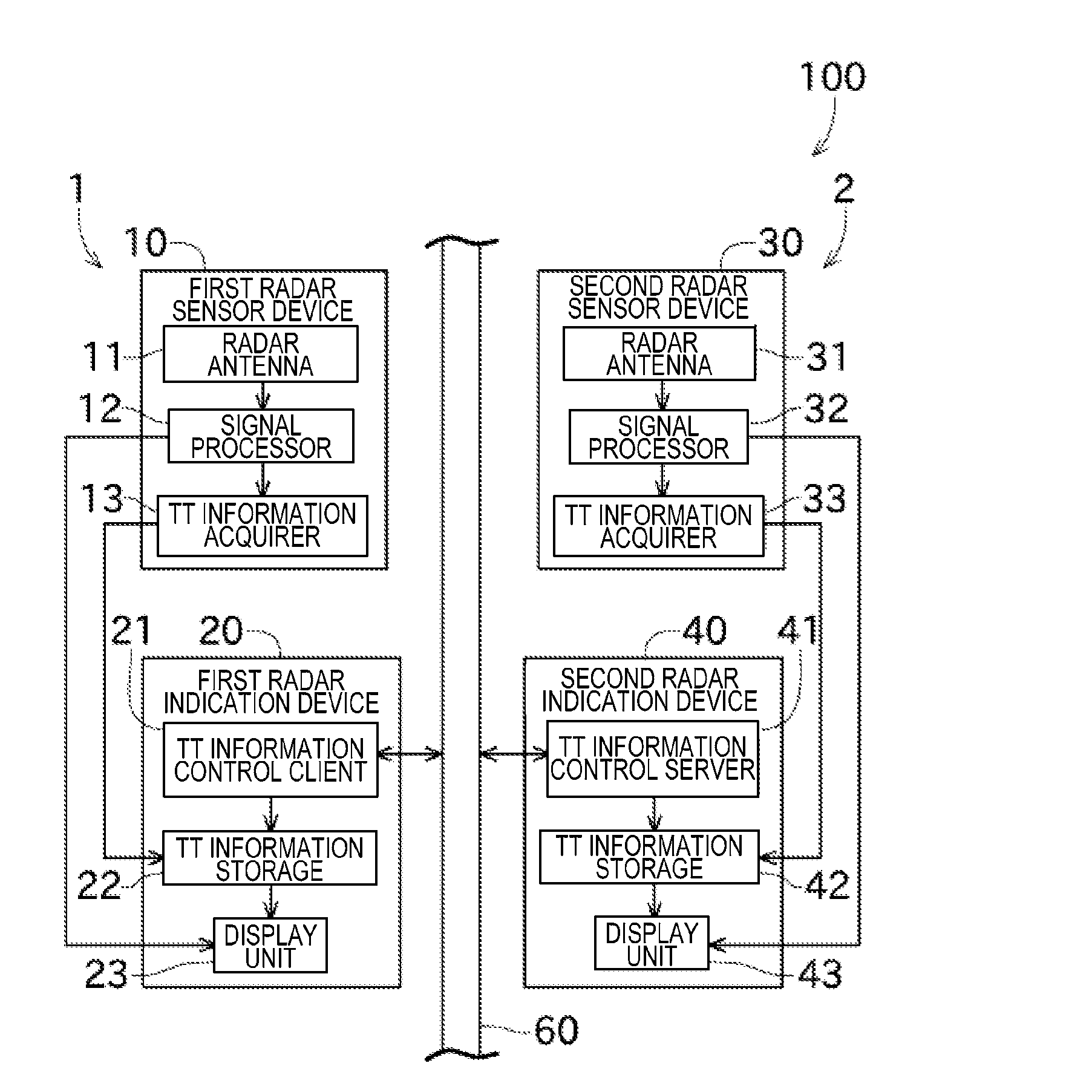
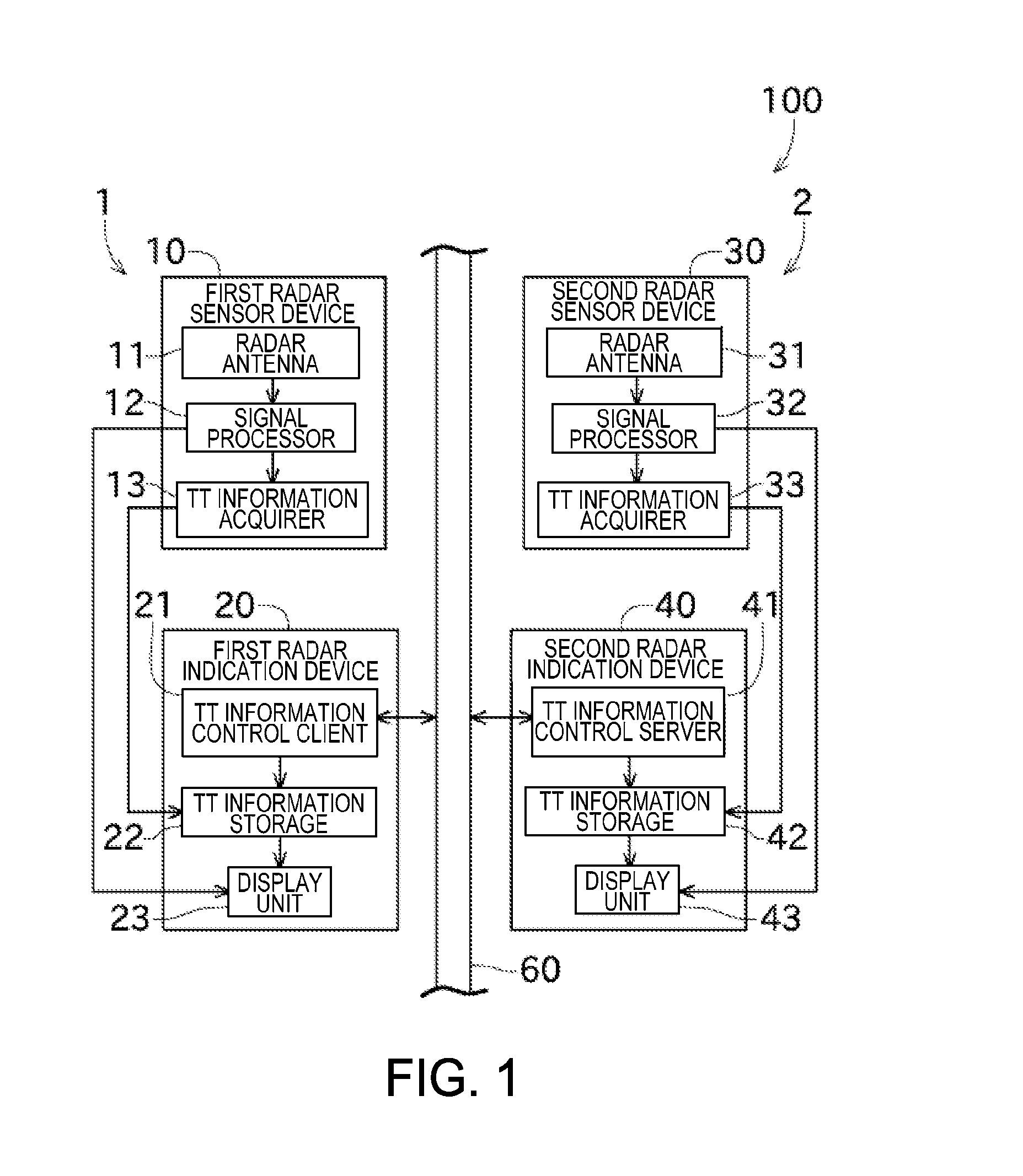
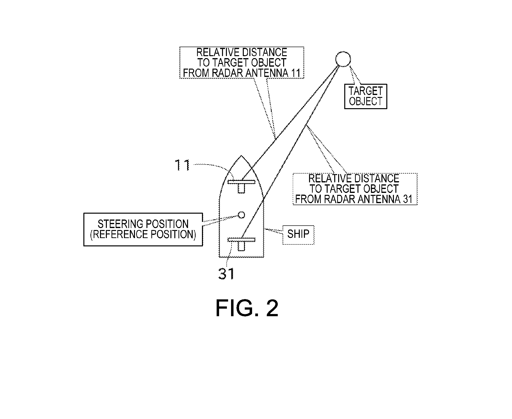
[0062]Next, an embodiment of the present invention is described with reference to the appended drawings. FIG. 1 is a block diagram showing a configuration of a TT information control system 100 (tracking information control system) according to this embodiment. FIG. 2 is a view explaining a reference position for a relative position of a target object (hereinafter, may simply be referred to as “the reference position”).

[0063]The TT information control system 100 shown in FIG. 1 includes a first radar device 1 and a second radar device 2 connected with each other via a wired LAN 60 that allows a mutual communication between the devices. Note that, the number of radar devices constituting the TT information control system 100 is not limited to two and may be more.

[0064]First, the first radar device 1 and the second radar device 2 are explained. Note that, the first and second radar devices 1 and 2 are only partially different from each other (the first radar device 1 includes a TT inf...


PUM


Abstract

This disclosure provides a tracking information control device. The device includes a receiver for receiving, from two radar devices, data relating to a target echo received by a radar antenna of one of the radar devices, and data relating to a target echo received by a radar antenna of the other radar device, the data being obtained from tracking the target echoes, respectively, a determiner for determining whether the target echoes indicate the same target object, an ID applier for applying the same ID to the target echoes when the determiner determines that the target echoes indicate the same target object, and a transmitter for transmitting the same IDs to the radar devices in order to inform whether the target echoes displayed by the radar devices, respectively, indicate the same target object.

Description

CROSS-REFERENCE TO RELATED APPLICATION(S)[0001]The application claims priority under 35 U.S.C. §119 to Japanese Patent Application No. 2011-131233, which was filed on Jun. 13, 2011 the entire disclosure of which is hereby incorporated by reference.TECHNICAL FIELD[0002]The present invention relates to a tracking information control device for controlling tracking information that is obtained based on an echo acquired by a radar antenna.BACKGROUND OF THE INVENTION[0003]Conventionally, various navigation devices have been developed in view of prevention of collision between ships and safety of life. For example, a radar device having a TT (Target Tracking) function has been known as such a navigation device. Here, simply put, the TT function is for detecting a position and a velocity vector of a target object that exists around a ship concerned, based on a transition of a radar image obtained previously. JP2009-122063A discloses a configuration including two radar devices having the TT...

Claims


Application Information

Patent Timeline
Patent Type & Authority Applications(United States)
IPC IPC(8): G01S13/66
CPCG01S7/04G01S13/726G01S13/872G01S13/003G01S13/878
Inventor YANAGI, KATSUYUKI
Owner FURUNO ELECTRIC CO LTD
Why Eureka
Try Eureka