Backlight module

A backlight module and backplane technology, applied in optics, light guides, light sources, etc., can solve problems affecting the optical performance of the backlight module 100, falling off, and easy displacement of the first reflector

Inactive Publication Date: 2011-03-30
AU OPTRONICS CORP
View PDF0 Cites 14 Cited by
  • Summary
  • Abstract
  • Description
  • Claims
  • Application Information

AI Technical Summary

Problems solved by technology

[0007] However, the first reflective sheet 15 is directly pasted on the lower surface of the top 141 of the cover body 14 without any positioning device for positioning the first reflective sheet 15, so the first reflective sheet 15 is prone to position deviation during assembly.
In addition, after long-term use or under the action of improper external force, the first reflector 15 is easy to shift or fall off from the top 141 of the cover 14, which affects the optical performance of the backlight module 100.

Method used


Image

  • Backlight module
  • Backlight module
  • Backlight module

Examples


Embodiment Construction

[0024] In order to further explain the technical means and effects of the present invention to achieve the intended purpose of the invention, the specific implementation, structure, characteristics and effects of the backlight module proposed according to the present invention will be described in detail below in conjunction with the accompanying drawings and examples. As later.

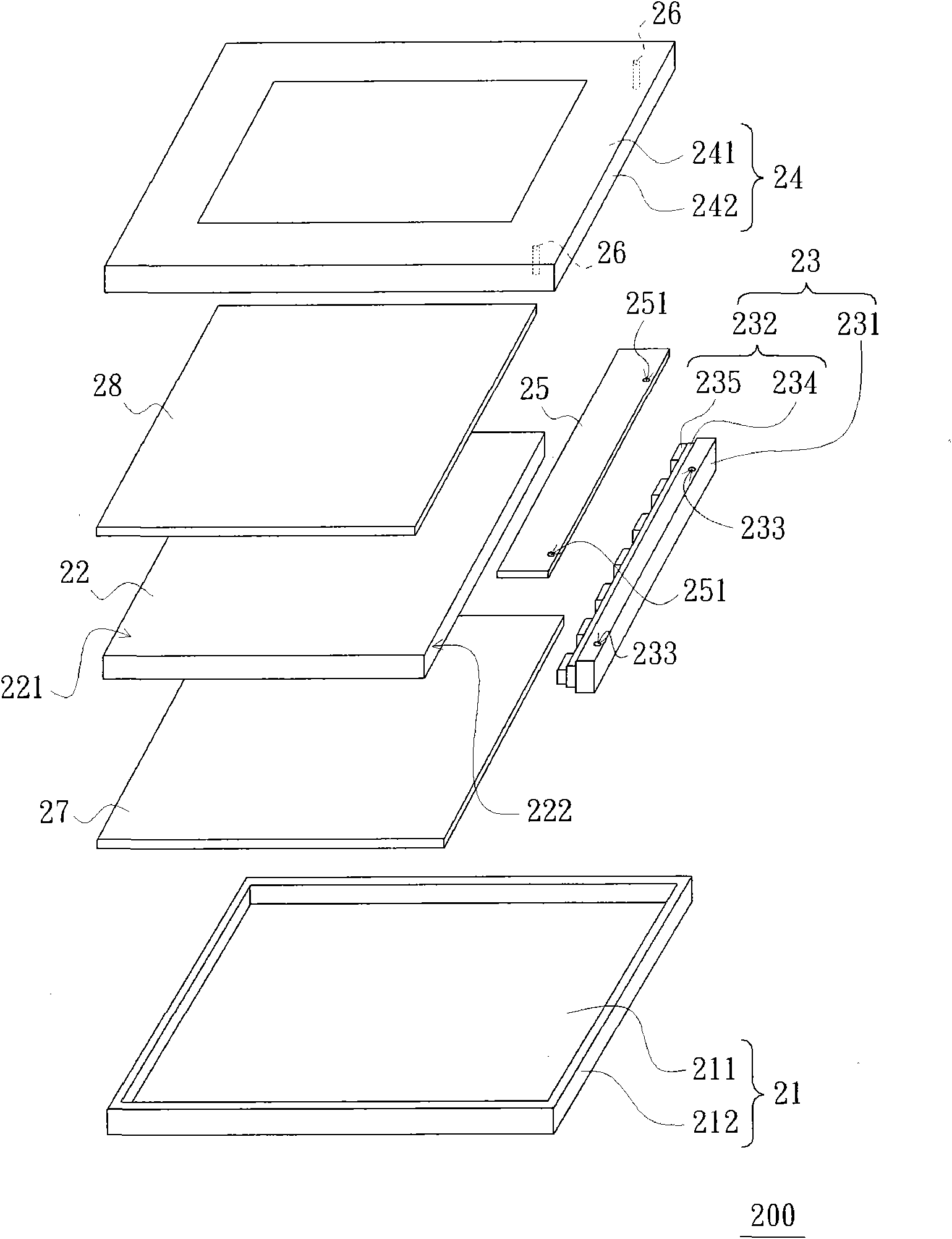
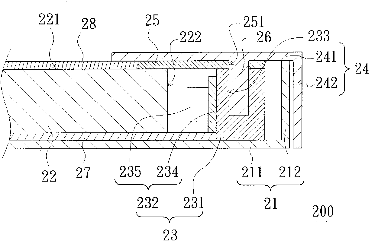
[0025] See figure 2 and image 3 , the backlight module 200 of this embodiment includes a backplane 21, a light guide plate 22, a light emitting device 23, a cover 24, a first reflection sheet 25, and at least one positioning member 26 ( figure 2 Two) and the second reflection sheet 27 are schematically shown.

[0026] The back plate 21 has a bottom plate 211 and side walls 212 connected to the bottom plate 211 . The light guide plate 22 is disposed on the bottom plate 211 , and the light guide plate 22 has a light emitting top surface 221 and a light incident side surface 222 adjacent to the li...


PUM


Abstract

The invention provides a backlight module. The backlight module comprises a back panel, a light guide panel, a fluorescent device, a cover, a reflector and a positioning part, wherein the back panel is provided with a bottom plate and a side wall connected to the bottom plate; the light guide panel is configured on the bottom plate, and is provided with an emergent roof and an incident side surface adjacent to the emergent roof; the fluorescent device is configured on the bottom plate and positioned between the incident side surface and the side wall, and comprises a heat radiating block and a fluorescent part, the heat radiating block is fixed on the bottom plate and a fluorescent part is configured on the heat radiating block and is suitable for emitting light towards the incident side surface; the cover is provided with a roof and a side part connected to the roof which is configured on the emergent roof and the fluorescent device and covers partial emergent roof; the side part and the side wall are arranged oppositely; the reflector is configured between the roof and the emergent roof and between the roof and the heat radiating block; a positioning part is fixed on the roof, and is inserted into the heat radiating block through the reflector; and the positioning part of the backlight module plays a role in positioning the reflector so as to prevent the reflector from displacing or falling.

Description

technical field [0001] The invention relates to a backlight module, in particular to a backlight module with a reflector positioning structure. Background technique [0002] The liquid crystal display panel of the liquid crystal display cannot emit light by itself, so there must be a backlight module to provide the surface light source required by the liquid crystal display panel. See figure 1 , a conventional backlight module 100 includes a backplane 11 , a light guide plate 12 , a light emitting device 13 , a cover 14 , a first reflection sheet 15 and a second reflection sheet 16 . [0003] The backplane 11 has a bottom plate 111 and side walls 112 connected to the bottom plate 111 . The light guide plate 12 is disposed on the bottom plate 111 , and the light guide plate 12 has a light emitting top surface 121 and a light incident side surface 122 adjacent to the light emitting top surface 121 . [0004] The light emitting device 13 is disposed on the bottom plate 111 o...

Claims


Application Information

Patent Timeline
Patent Type & Authority Applications(China)
IPC IPC(8): F21S8/00F21V7/00F21V8/00F21V11/00F21V17/00F21V29/00G02F1/13357F21Y101/02F21V23/00
Inventor 庄政儒陈信利
Owner AU OPTRONICS CORP
Why Eureka
Try Eureka