Pattern forming method and pattern forming apparatus

a pattern and forming method technology, applied in the field of pattern forming methods and forming apparatuses, can solve problems such as ink blues, and achieve the effects of improving the quality of the edge portions of the pattern, preventing deviation in the dot position, and improving the quality of the pattern (image formation quality)

Inactive Publication Date: 2013-08-08
FUJIFILM CORP
View PDF15 Cites 14 Cited by
  • Summary
  • Abstract
  • Description
  • Claims
  • Application Information

AI Technical Summary

Benefits of technology

[0073]According to the present invention, by carrying out modification treatment on a treatment target region corresponding to a pattern to be formed on a pattern forming surface of a base body, then even if there is deviation in landing positions of dots, the dots are drawn to prescribed positions and therefore deviation in the dot positions is prevented and combination of the dots due to the deviation in the dot positions is also prevented. Furthermore, by carrying out the modification treatment with a light beam having a width smaller than the diameter of each dot, the fixing positions of the dots are adjusted at the order of the width of the light beam, and therefore the quality of the pattern (image formation quality) is improved. In particular, jaggedness occurring in the edge portions of the pattern (the respective end portions of the pattern in the width direction) is adjusted to the width of the modification treatment, and therefore such jaggedness is not readily visible and the quality of the edge portions of the pattern is improved. Moreover, by determining distortion of the substrate and accordingly changing the modification pattern, it is possible to correct deviation of the pattern, on demand, and the quality of image formation can be improved.

Problems solved by technology

An issue involved in the pattern image forming using the inkjet method is blurring of the ink due to the occurrence of bulging (clumping) which arises when a plurality of droplets deposited on a substrate combine together, and due to the occurrence of jagged edges caused by deviation in the direction of flight of the droplets or movement of the droplets which have been deposited on the substrate.

Method used


Image

  • Pattern forming method and pattern forming apparatus
  • Pattern forming method and pattern forming apparatus
  • Pattern forming method and pattern forming apparatus

Examples


second embodiment

[0248]Next, a second embodiment of the present invention is described. FIG. 20 is a perspective diagram showing an approximate composition of a pattern forming apparatus 300 according to the second embodiment of the present invention, and FIG. 21 is a side view diagram showing the pattern forming apparatus 300 depicted in FIG. 20 as viewed from a side of a side face of a conveyance drum 301.

[0249]The pattern forming apparatus 300 according to the present embodiment includes: a light application head 326, which carries out modification treatment on an outer circumferential surface of the transfer drum 301 (base body); an inkjet head 334, which is arranged so as to eject and deposit droplets of liquid (liquid containing functional material), such as wiring ink or resin ink, onto the outer circumferential surface of the transfer drum 301 which has undergone the modification treatment; a sensor 314, which determines distortion of a substrate 302; and a conveyance mechanism (shown and de...

third embodiment

[0272]Next, a third embodiment of the present invention is described. FIG. 23 is a conceptual drawing of a droplet deposition processing step in the pattern forming method according to the third embodiment. In the following description, parts which are the same as or similar to the parts described above are denoted with the same reference numerals and further explanation thereof is omitted here.

[0273]The droplet deposition processing step shown in FIG. 23 includes a temperature control step which controls temperature of the substrate 10 (the pattern forming surface 10A). FIG. 23 shows a mode where the substrate 10 is heated by a heater 19 from the rear surface (the surface reverse to the pattern forming surface 10A) of the substrate 10.

[0274]Instead of the heater 19 shown in FIG. 23, it is also possible to adopt a mode which includes a Peltier element or a mode which heats the substrate 10 from the side of the pattern forming surface 10A of the substrate 10. Moreover, a desirable mo...

fourth embodiment

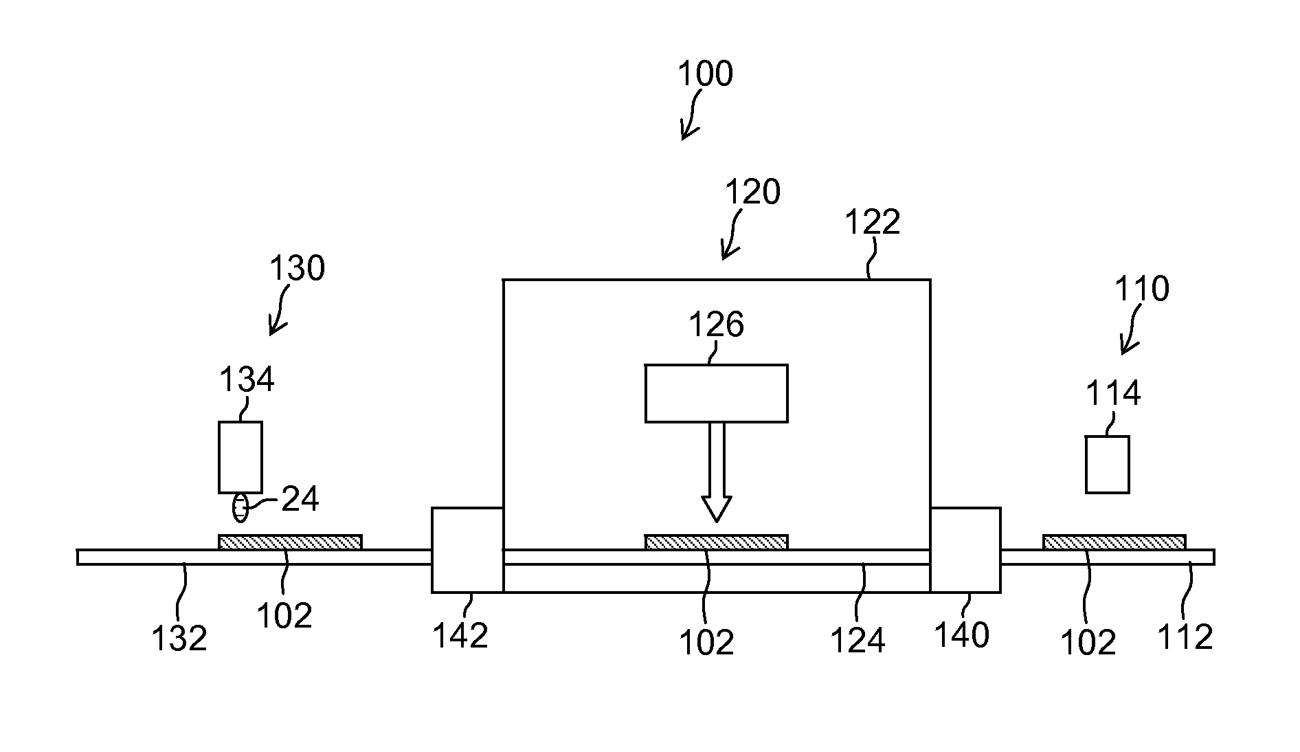
[0284]Next, a fourth embodiment of the present invention is described. FIG. 26 is a schematic drawing showing an approximate composition of a pattern forming unit 130 in a pattern forming apparatus 100″ according to a fourth embodiment. In the pattern forming unit 130 shown in FIG. 26, an inkjet head 134 and an auxiliary light application unit 135 are mounted on a carriage 150.

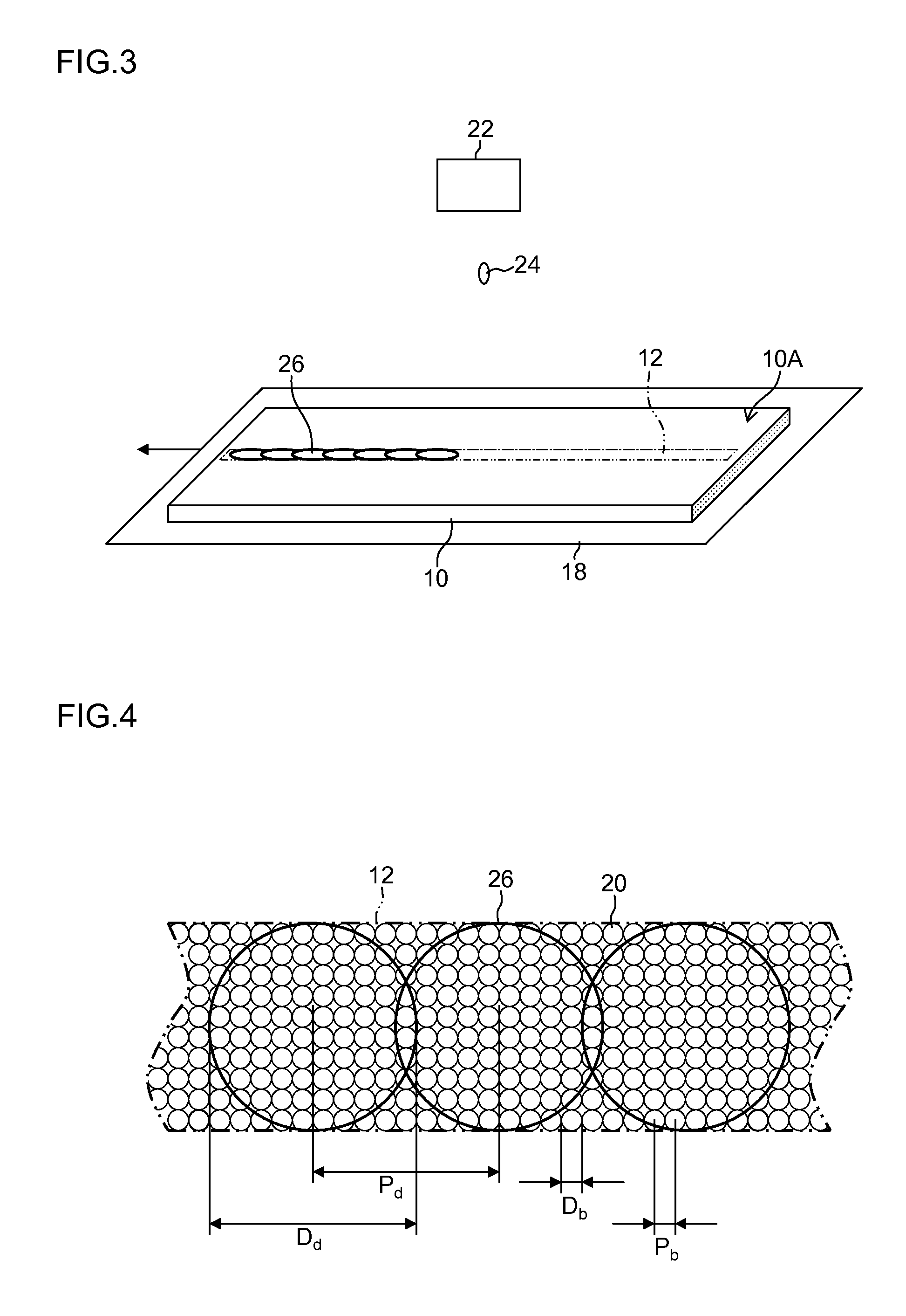
[0285]The present embodiment employs a liquid of which the viscosity is raised by irradiation with the auxiliary light. The auxiliary light application unit 135 applies the auxiliary light to the droplets (dots 26) which have landed on the substrate 102, thereby raising the viscosity of the dots 26.

[0286]The auxiliary light can employ light having a wavelength from the visible light region to the ultraviolet light region. When an ultraviolet-curable ink, which is cured by irradiation with ultraviolet light is used as the liquid which is ejected from the inkjet head 134, then ultraviolet light is employed as th...


PUM

PropertyMeasurementUnit
diameteraaaaaaaaaa
sizeaaaaaaaaaa
diameteraaaaaaaaaa

Abstract

A pattern forming method includes: a modification treatment step of, in accordance with a pattern to be formed on a pattern forming surface of a base body, applying a light beam having a width smaller than a diameter of each of dots to constitute the pattern, onto a treatment target region including at least outer edges on both sides in a width direction of a region where the pattern is to be formed in the pattern forming surface, thereby carrying out modification treatment on the treatment target region; and a droplet deposition step of ejecting and depositing droplets of a functional liquid by an inkjet method onto the region where the pattern is to be formed including the treatment target region where the modification treatment has been carried out.

Description

TECHNICAL FIELD[0001]The present invention relates to a pattern forming method and a pattern forming apparatus, and more particularly to fine pattern forming technology using an inkjet method.BACKGROUND ART[0002]In recent years, attention has focused on technology for forming fine patterns such as an electrical wire pattern and mask pattern on the substrate, by using a liquid ejection head (inkjet head) based on an inkjet method. For example, by ejecting droplets of liquid in which metal particles or resin particles are dispersed, from an inkjet head so as to place the droplets on a substrate, a pattern image is formed on a substrate by the liquid, and this pattern is cured by heating or the like, thereby forming an electric wire pattern or a mask pattern. An issue involved in the pattern image forming using the inkjet method is blurring of the ink due to the occurrence of bulging (clumping) which arises when a plurality of droplets deposited on a substrate combine together, and due...

Claims


Application Information

Patent Timeline
Patent Type & Authority Applications(United States)
IPC IPC(8): B41J2/045
CPCH05K3/125H05K3/1283H05K2203/107B41J2/04505Y10T29/49155B41J3/407B41J11/0015B41J2002/012B41J2/01B05C5/00B05C9/10B05D1/26B05D3/06
Inventor KODAMA, JUN
Owner FUJIFILM CORP
Why Eureka
Try Eureka