Eureka AIR delivers breakthrough ideas for toughest innovation challenges, trusted by R&D personnel around the world.

Thermal analysis apparatus

Inactive Publication Date: 2007-08-30
SII NANOTECHNOLOGY INC
View PDF6 Cites 15 Cited by
  • Summary
  • Abstract
  • Description
  • Claims
  • Application Information

AI Technical Summary

Benefits of technology

[0010] According to the thermal analysis apparatus concerned with this invention, by the fact that while the heating furnace is fixed to the support base by the heating furnace fixation part, also the furnace tube is fixed in its base end part to the support base by the fixation member, the furnace tube keeps a state in which it has been inserted through the heating furnace while having the interstice. And, the heating furnace is raised in its temperature with the sample being disposed by the sample holding means in the inside of the heating part of the furnace tube. The sample is heated in the inside of the furnace tube and, following upon this, by measuring a temperature of the sample by the temperature measurement means, it is possible to evaluate a temperature characteristic of the sample. On this occasion, by raising the heating furnace in its temperature, the furnace tube is also heated, and the furnace tube generates an expansion or a contraction in an axial direction and a radial direction. By the fact that the furnace tube is fixed in its base end part by the fixation member and can expand or contract in the axial direction by the fixation means, even if the temperature has changed, it is possible to freely expand or contract in the axial direction without the fact that a stress occurs. On the other hand, by the fact that, in the radial direction, it is positioned and fixed by the fixation means, a positional deviation in the radial direction following upon the temperature change is prevented, and a position of the sample in the radial direction in the inside of the furnace tube is made constant, so that a heating environment of the sample can be kept always constant.
[0012] According to the thermal analysis apparatus concerned with this invention, by the fact that it is positioning-fixed in the radial direction by the fixation means in both sides of the heating part of the furnace tube in which the expansion or the contraction occurs due to the temperature change, the positional deviation to the radial direction following upon the temperature change can be more certainly prevented.
[0014] According to the thermal analysis apparatus concerned with this invention, both the furnace tube to be heated and the heating furnace which heats the furnace tube are fixed to the support base through the heating furnace fixation part, i.e., fixed by the same fixation system. Therefore, a relative positional relation between the heating furnace and the furnace tube can be kept constant, so that the heating environment of the sample can be additionally stabilized.
[0018] According to the thermal analysis apparatus concerned with this invention, by the fact that the butting member butting-supported to the furnace tube is the columnar piece approximately like the column, a contact with the furnace tube is made a line contact, so that there can be fixed with a contacting range being made minimum. Therefore, it is possible to suppress a heat transfer from the furnace tube to the columnar piece, the sample can be efficiently heated, and it is possible to prevent the columnar piece, which is the butting member, or the fixation bolt from being heated and expanding or contracting.
[0020] According to the thermal analysis apparatus concerned with this invention, by the fact that the columnar piece is formed by ceramics, it is possible to additionally suppress the heat transfer to the columnar piece, the sample can be efficiently heated, and it is possible to suppress the expansion or the contraction of the columnar piece by the fact that it is heated.
[0024] According to the thermal analysis apparatus concerned with this invention, there is no fact that the furnace tube position-deviates in the radial direction following upon the temperature change, and it is possible to precisely measure a weight change following upon the temperature change of the sample by heating the sample in a constant heating environment.

Problems solved by technology

Therefore, in a case where the furnace tube has position-deviated in the radial direction, there has been a problem that a heating environment of the sample changes, so that a precise measurement becomes impossible to be performed.

Method used


Image

  • Thermal analysis apparatus
  • Thermal analysis apparatus
  • Thermal analysis apparatus

Examples


Embodiment Construction

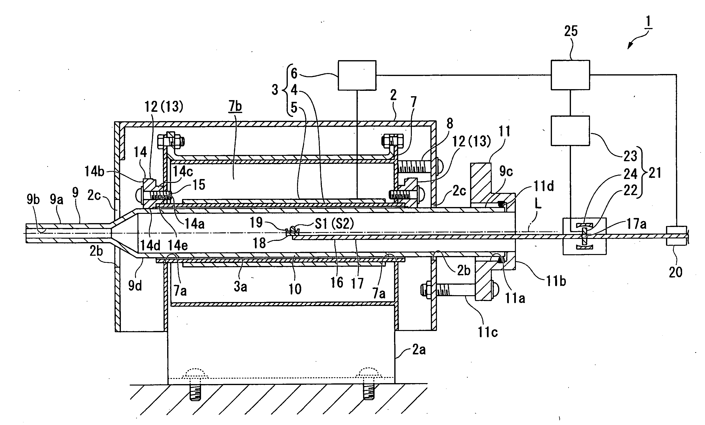
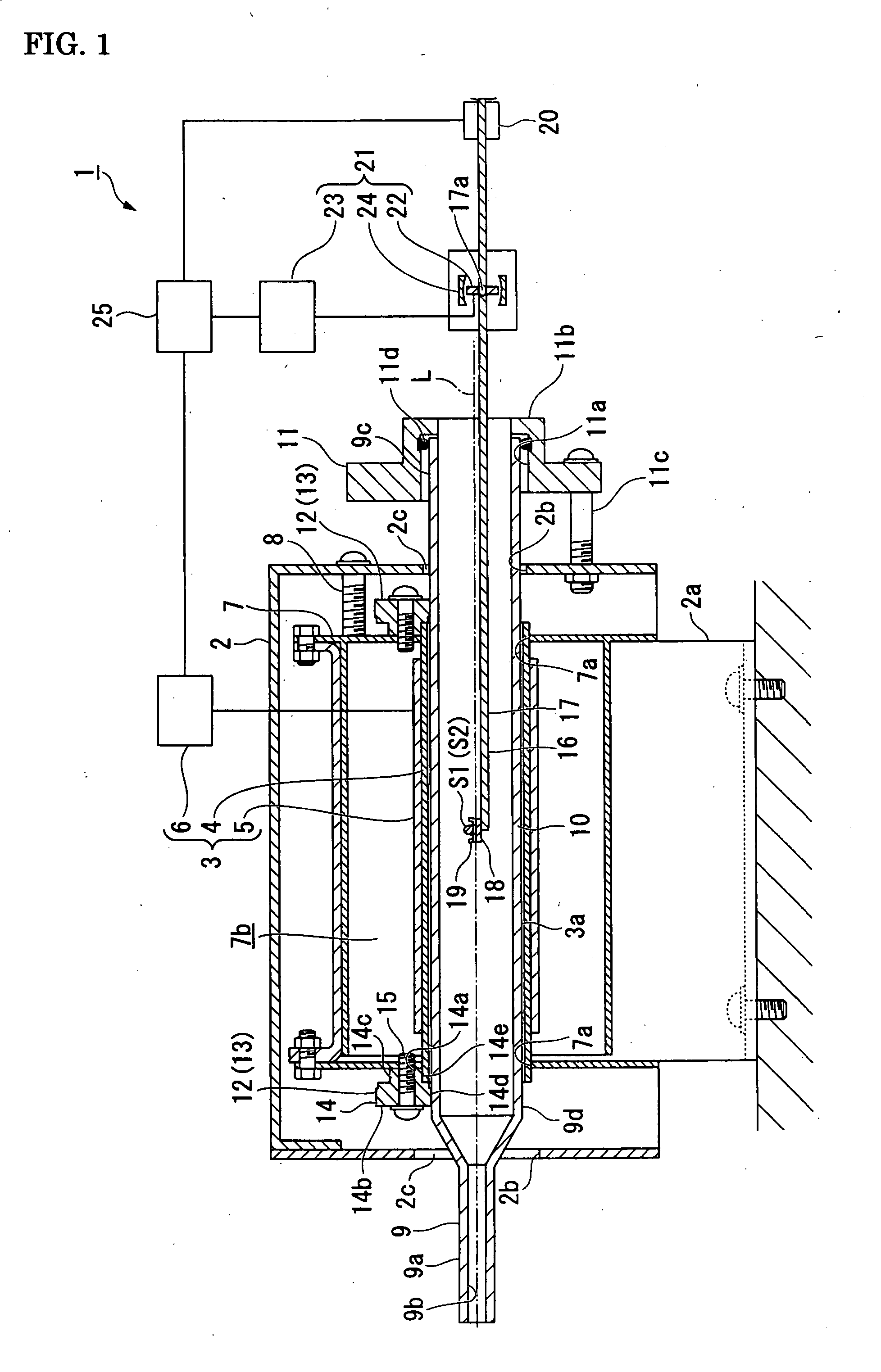
[0032]FIG. 1 to FIG. 4 show an embodiment concerned with this invention. A thermal analysis apparatus 1 of this embodiment is a differential thermal / thermogravimetric simultaneous measurement apparatus in which different samples of a measurement sample S1 and a reference sample S2 are heated in a constant heating environment, respective temperature changes are measured, and weights of the measurement sample S1 and the reference sample S2 are measured. Here under, details are shown about its constitution.

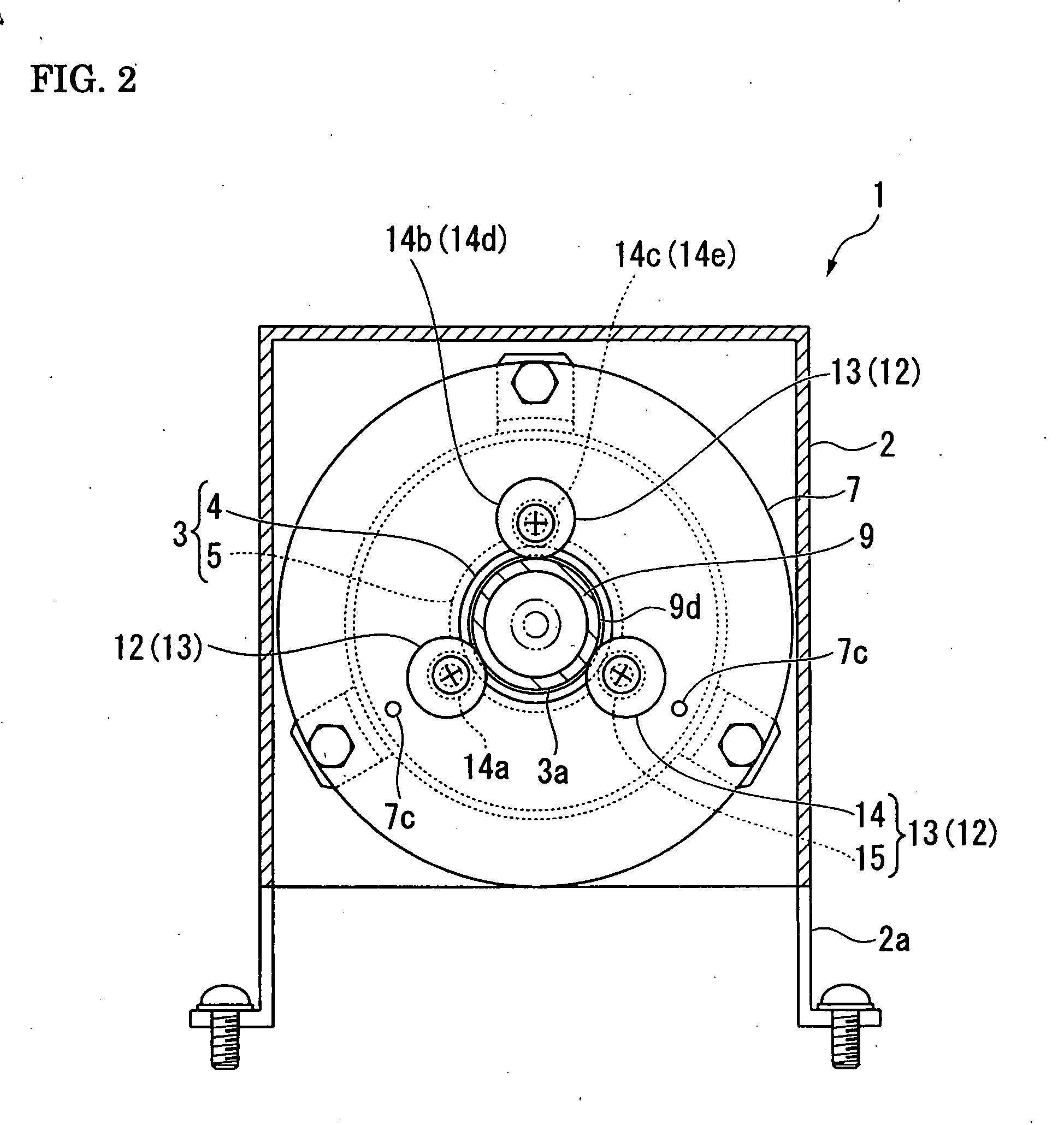
[0033] As shown in FIG. 1 and FIG. 2, the thermal analysis apparatus 1 possesses an outer casing 2 functioning as a support base capable of being fixed to a predetermined installation position, and a heating furnace 3 having been accommodated in an inside of the outer casing 2. The heating furnace 3 possesses an approximately cylindrical furnace core tube 4, a heater 5 which is approximately cylindrical and has been externally fitted to the furnace core tube 4, and a heater drive se...


PUM


Abstract

A thermal analysis apparatus possesses a support base, a heating furnace which is approximately like a cylinder, and whose inside can be raised in its temperature, till a predetermined heating temperature, a heating furnace fixation part fixing the heating furnace to the support base, a furnace tube which is approximately like the cylinder, inserted through the heating furnace while having an interstice, and has been fixed in its base end part to the support base by a fixation member, a fixation means which makes the furnace tube capable of expanding or contracting in an axial direction, and positioning-fixes it in a radial direction, a sample holding means which holds a sample in an inside of a heating part of the furnace tube, that is a range capable of being heated by the heating furnace, and a temperature measurement means measuring a temperature change of the sample.

Description

BACKGROUND OF THE INVENTION [0001] The present invention relates to a thermal analysis apparatus in which a sample is heated and a physical change of the sample following upon a temperature change is measured. [0002] From olden times, as a method of evaluating a temperature characteristic of the sample, there is performed a method called a thermal analysis in which the sample is heated and the physical change of the sample following upon the temperature change is measured. As the thermal analysis like this, from its object, although various methods are proposed, there are, e.g., a differential thermal analysis in which the sample and a reference material are heated while being juxtaposed and a relative change in a temperature is measured, a thermogravimetric analysis in which a weight change of the sample following upon the temperature change is measured, and the like. [0003] For example, as an apparatus for performing the thermogravimetric analysis, there is proposed a thermal anal...

Claims


Application Information

Patent Timeline
IPC IPC(8): G01N25/00G01K17/00
CPCG01N25/00G01G1/00G01N5/00G01N5/04
Inventor TAKEUCHI, TOSHITADAHASUDA, MASAKATSU
Owner SII NANOTECHNOLOGY INC
Why Eureka
Eureka Blog
Learn More