

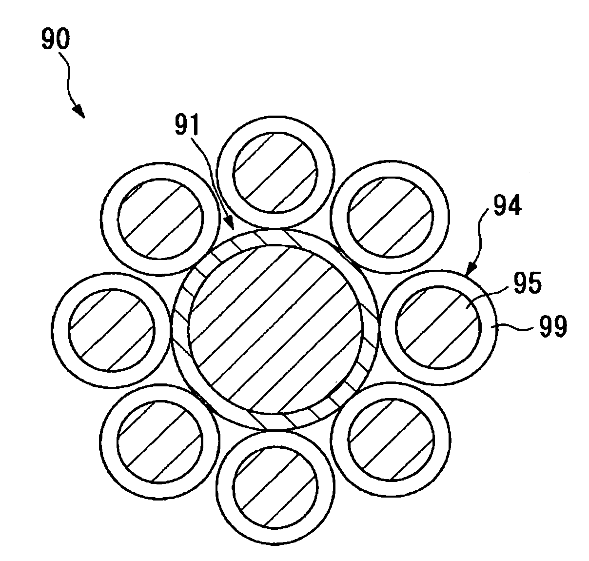
Anisotropically conductive adhesive comprising crushable microcapsules adhered to a surface of conductive particles
a technology of anisotropic conductive adhesive and crushed microcapsules, which is applied in the direction of non-conductive materials with dispersed conductive materials, synthetic resin layered products, natural mineral layered products, etc., can solve the problems of difficult preparation of microcapsules, inability to cure the rest of the adhesive separated from crushed microcapsules, etc., and achieve reliable electrical connection
- Summary
- Abstract
- Description
- Claims
- Application Information
AI Technical Summary
Benefits of technology
Problems solved by technology
Method used
Image

Examples
Embodiment Construction
[0028]Embodiments of the present invention will now be described with reference to the drawings, in which the scale of each component is properly changed for visibility.
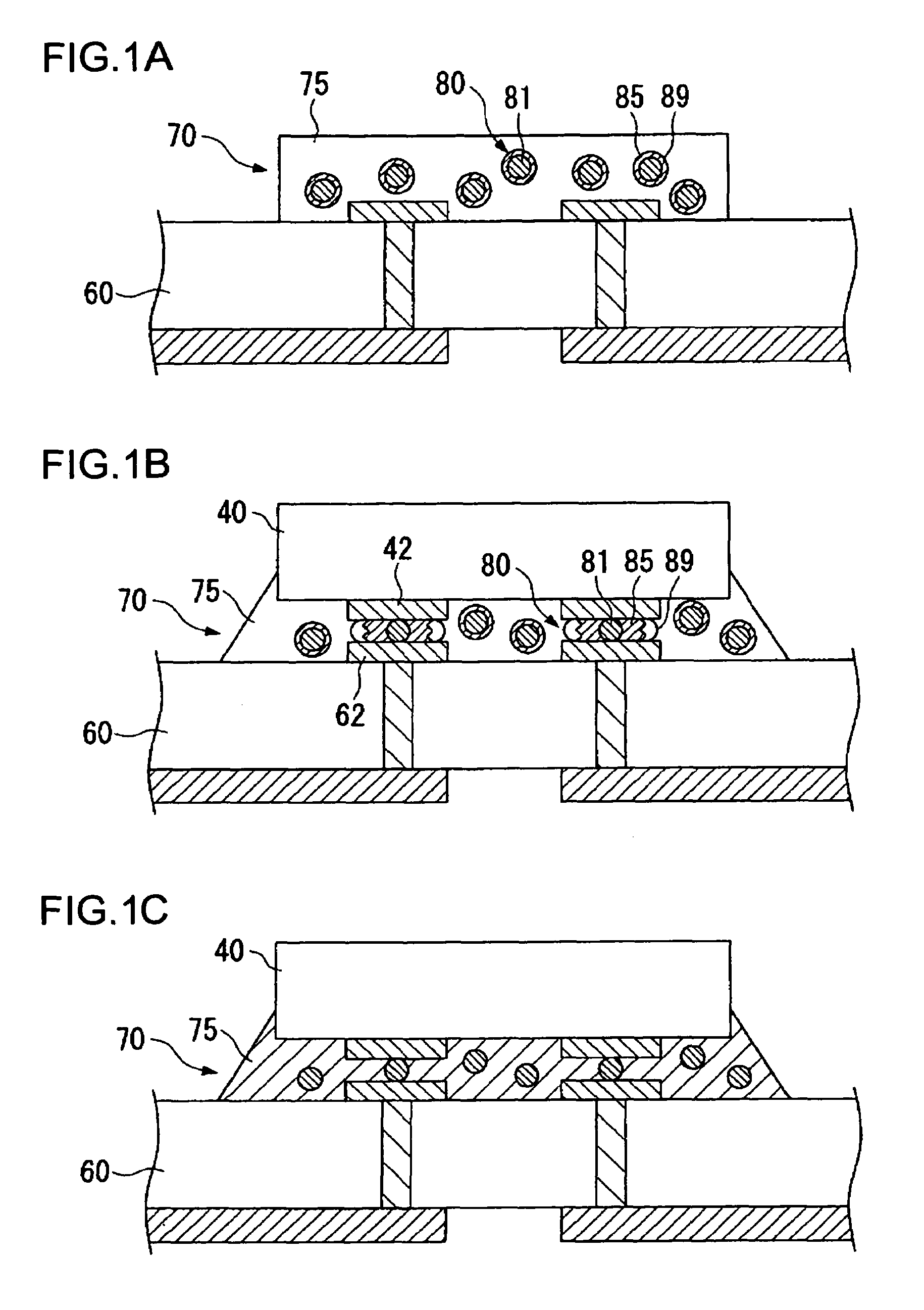
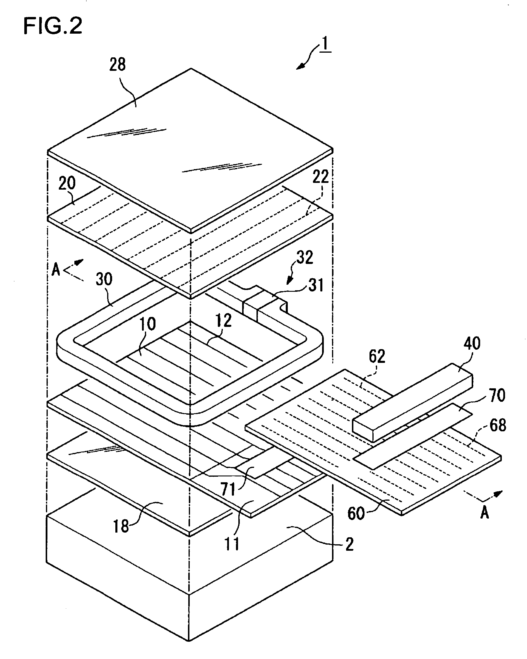
[0029]A liquid crystal display module, as an embodiment of electro-optical device modules according to the present invention, will now be described with reference to FIGS. 2 and 3. FIG. 2 is an exploded perspective view of this liquid crystal display module. FIG. 3 is a sectional side view taken along line A—A in FIG. 2. This liquid crystal display module is mainly composed of a liquid crystal display panel 1, an FPC 60 mounted on the liquid crystal display panel 1, and a drive IC 40 mounted on the FPC 60. In this embodiment, the liquid crystal display panel 1 is a passive matrix display panel, though the present invention may also apply to an active matrix display panel. It should be understood that this liquid crystal display module is only schematically illustrated in FIGS. 2 and 3, in practice it has more compone...
PUM
| Property | Measurement | Unit |
|---|---|---|
| Electrical conductor | aaaaa | aaaaa |
Abstract
Description
Claims
Application Information