
Outer conductor terminal and shield connector

a technology of outer conductor terminal and shield connector, which is applied in the direction of coupling device connection, securing/insulating coupling contact member, two-part coupling device, etc., can solve the problems of return current corresponding to an electrical signal of the inner conductor terminal not flowing smoothly from the outer conductor terminal body, and the shielding property can be impaired, so as to improve the reliability of electrical connection between the lid and the body

Active Publication Date: 2020-08-27
SUMITOMO WIRING SYST LTD
View PDF0 Cites 7 Cited by
  • Summary
  • Abstract
  • Description
  • Claims
  • Application Information

AI Technical Summary

Benefits of technology

The patent text describes how a lid is securely closed on a body using a lock mechanism. The mechanism involves sandwiching the lock between the front and rear of the body and applying a force to keep it closed. This ensures a reliable connection between the lid and the body, improving the reliability of the electrical connection.

Problems solved by technology

However, a shielding property can be impaired by the cut and raised lock projection and by a bored part such as the lock hole in the outer conductor terminal.
Further, in the case of connecting the lid to a circuit board, a return current corresponding to an electrical signal of the inner conductor terminal may not flow smoothly from the outer conductor terminal body to the lid unless a contact point between the lock projection and the lock hole is established reliably.

Method used


Image

  • Outer conductor terminal and shield connector
  • Outer conductor terminal and shield connector
  • Outer conductor terminal and shield connector

Examples


Embodiment Construction

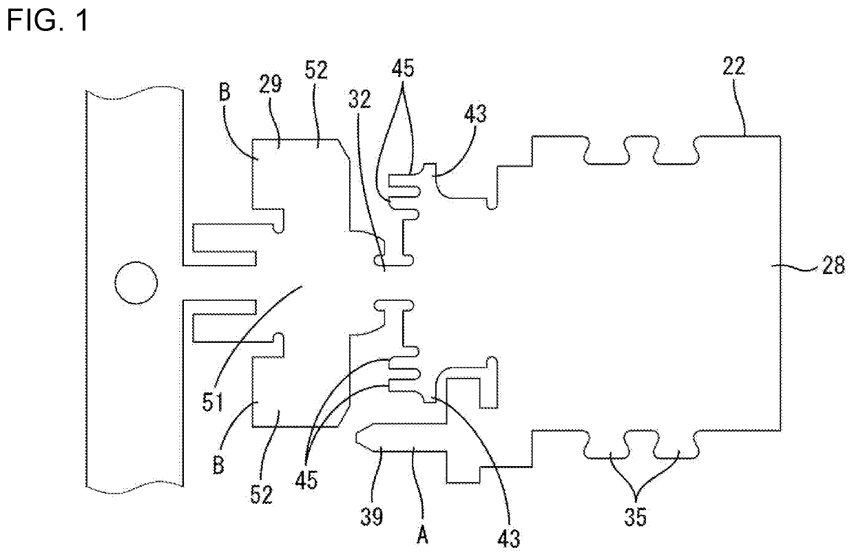
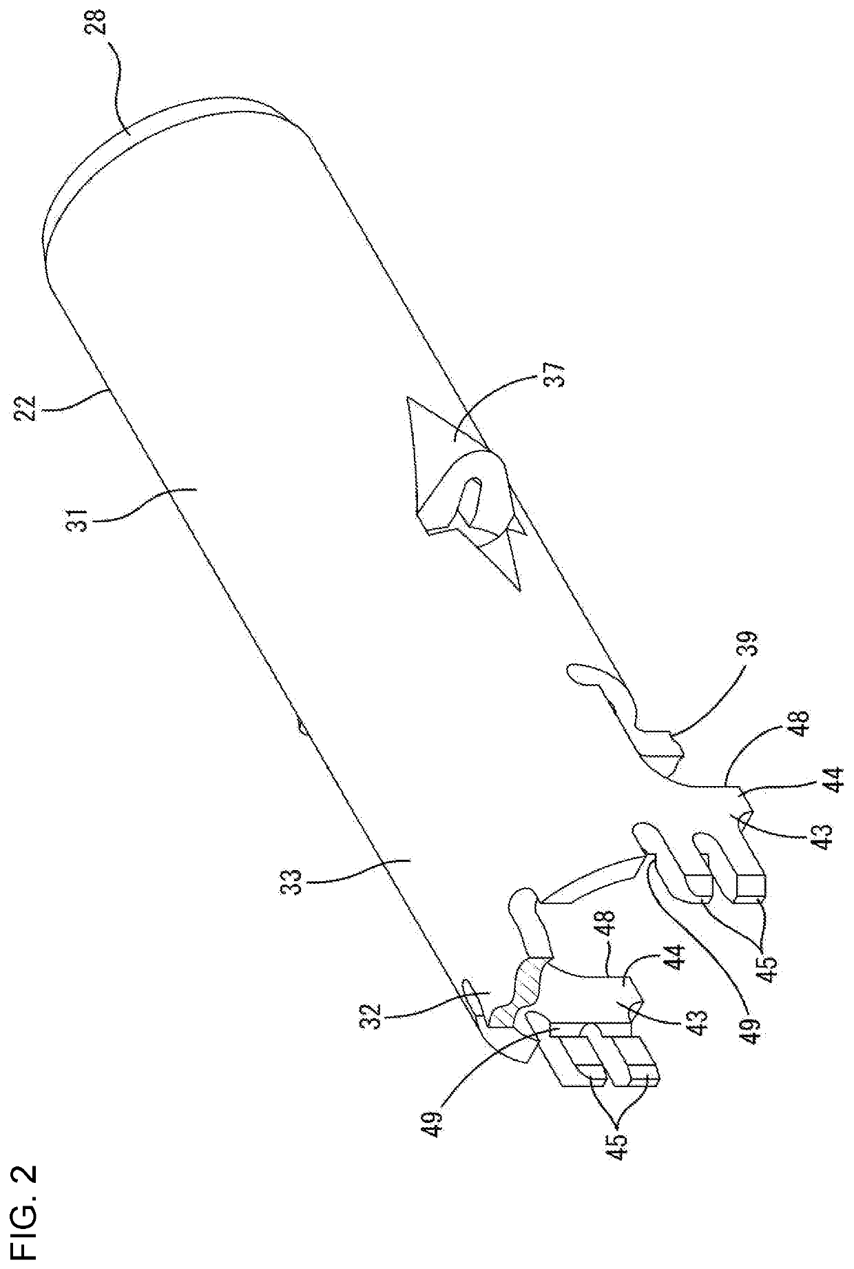
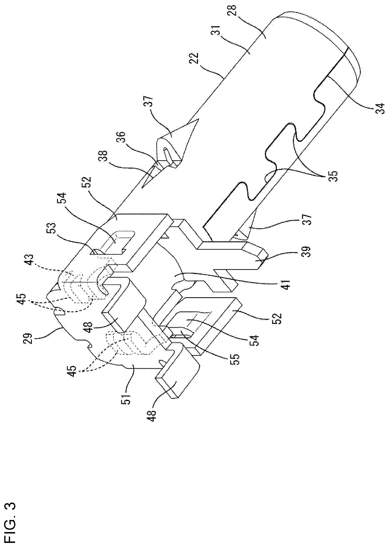
[0020]One embodiment of the invention is described with reference to FIGS. 1 to 10. A shield connector 10 of this embodiment is installed in an unillustrated automotive vehicle and is used in high-speed communication between in-vehicle electrical components. In the following description, a left side of FIGS. 8 to 10 is referred to as a front concerning a front-rear direction and upper and lower sides are based on a vertical direction of FIG. 8.

[0021]As shown in FIG. 8, the shield connector 10 includes a shield terminal 20 and a connector housing 60 for accommodating the shield terminal 20. The shield terminal 20 includes an inner conductor terminal 21, an outer conductor terminal 22 surrounding the outer periphery of the inner conductor terminal 21 and a dielectric 23 interposed between the outer conductor terminal 22 and the inner conductor terminal 21.

[0022]The inner conductor terminal 21 is formed, such as by bending a conductive metal plate. As shown in FIGS. 8 and 9, a tab 24 p...


PUM


Abstract

An outer conductor terminal (22) includes a body (28) surrounding an outer periphery of an inner conductor terminal (21) and having a rear opening and a lid (29) for closing the opening of the body (28). Body-side locks (43) are provided on side surfaces of the body (28). The lid (29) has side portions (52) for covering the side surfaces of the body (28). The side portions (52) are provided with front abutting portions (54) contacting the body-side locks (43) from the front. The lid (29) has rear abutting portions (56) contacting the body-side locks (43) from behind to sandwich the body-side lock portions (43) between the front abutting portions (54) and the rear abutting portions (56) and to hold the lid (29). The body-side locks (43) include contact portions (45) that contact the rear abutting portions (56) with resilient forces.

Description

BACKGROUNDField of the Invention[0001]The invention relates to an outer conductor terminal and a shield connector.Related Art[0002]Japanese Unexamined Patent Publication No. 2008-192474 discloses a shield terminal including an inner conductor terminal, an outer conductor terminal surrounding the outer periphery of the inner conductor terminal and a dielectric interposed between the outer conductor terminal and the inner conductor terminal. The shield terminal is accommodated into a connector housing. The outer conductor terminal is composed of an outer conductor terminal body covering the inner conductor terminal and a lid for closing an opening on a back surface of the outer conductor terminal body. The outer conductor terminal body includes board mounting tabs projecting down on four corners. The lid is fit externally on a rear part of the outer conductor terminal body.[0003]It is preferable to provide a locking structure between the outer conductor terminal body and the lid to re...

Claims


Application Information

Patent Timeline
Patent Type & Authority Applications(United States)
IPC IPC(8): H01R13/6581H01R13/6594H01R13/502
CPCH01R13/6594H01R13/6581H01R13/502H01R13/40H01R13/6591H01R24/50H01R2103/00H01R2201/26
Inventor HASHIMOTO, NORIHITOKANEMURA, KEISUKEKUBOTA, MOTOKIKANG, LIPINGMITSUI, SHOHEIYAMANAKA, WATARUKASUGA, MASANOBUHIRANO, AIWAKAHARA, SHINOBU
Owner SUMITOMO WIRING SYST LTD
Learn More