
Method for constructing universal LED bulb, flange inner snap ring type LED bulb and lamp

a technology of led bulbs and flanges, applied in the direction of lighting support devices, light source combinations, ways, etc., can solve the problems of high manufacturing cost, inconvenience for use, maintenance difficulties, etc., and achieve the effect of reducing the production procedures of led lighting products, ensuring the safety of use, and very stable structur

Inactive Publication Date: 2015-07-23
GUIZHOU GUANGPUSEN PHOTOELECTRIC
View PDF0 Cites 9 Cited by
  • Summary
  • Abstract
  • Description
  • Claims
  • Application Information

AI Technical Summary

Benefits of technology

The present invention provides a method for constructing a universal LED bulb, a flange inner snap ring type LED bulb and a lamp. It is simple and stable in structure, convenient to install, and can be used flexibly with various products such as lamps and lighting controls. This method simplifies the production procedures of LED lighting products, improves mass production, and facilitates the industrialization of LED energy-saving lighting products.

Problems solved by technology

This brings a series of fatal problems to the LED lighting products, such as high manufacturing cost, inconvenience for use, maintenance difficulty, and the like.
First of all, national and even global uniform standardized production could not be achieved on manufacture, leading to numerous product specifications, few batches and high prices; second, the products of producers are varied, not universal, let alone interchangeable; third, the LED light module, the driving power supply, the lighting fitting and the like need to be integrally detached for maintenance in the case of product failure, thus the maintenance is very inconvenient, and such defects as expanded failure, delayed maintenance and high maintenance cost and the like are very liable to form.
These defects greatly restrict the popularization and use of LED lighting and are inherent problems in the popularization of the LED lighting products.

Method used


Image

  • Method for constructing universal LED bulb, flange inner snap ring type LED bulb and lamp
  • Method for constructing universal LED bulb, flange inner snap ring type LED bulb and lamp
  • Method for constructing universal LED bulb, flange inner snap ring type LED bulb and lamp

Examples


embodiment 1-1

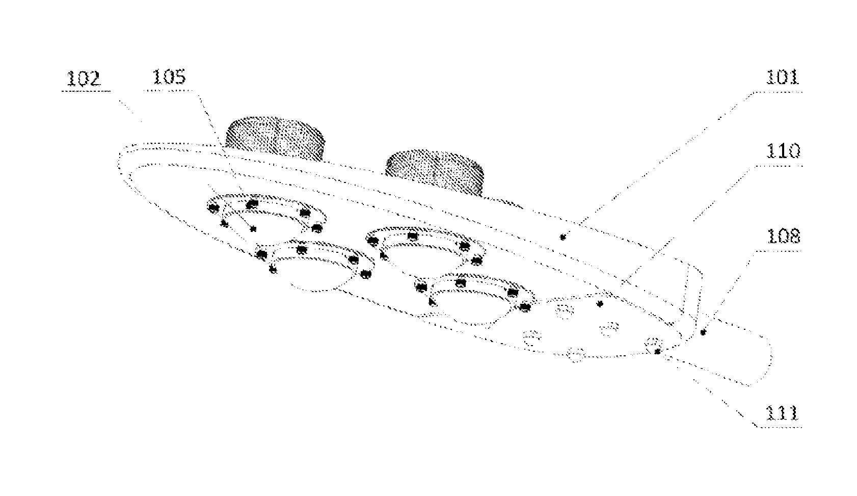
[0171]An LED tunnel lamp using an extrusion type double-faced radiator structure, including a metal extrusion type double-faced radiator 103 formed by an extrusion process, wherein an LED bulb 102 is provided on the extrusion type double-faced radiator 103, and a lamp housing 101 punch-formed by a metal or die-cast by plastics is provided outside the extrusion type double-faced radiator 103; the extrusion type double-faced radiator 103 is installed on an installation support 106, and an installation interface used for installing the LED bulb 102 is provided on the extrusion type double-faced radiator 103. The extrusion type double-faced radiator 103 includes a substrate, and fins are provided on two sides of the substrate; the installation interface used for installing the LED bulb 102 is provided at one side of the substrate, and circular or elliptic conical spaces are formed by cutting the fins around the installation interface of the substrate according to the illumination angle ...

embodiment 1-2

[0172]An LED street lamp using an extrusion type double-faced radiator structure, as shown in FIG. 34, including a metal extrusion type double-faced radiator 103 formed by an extrusion process, wherein an LED bulb 102 is provided on the extrusion type double-faced radiator 103, and a lamp housing 101 punch-formed by a metal or die-cast by plastics is provided outside the extrusion type double-faced radiator 103; the extrusion type double-faced radiator 103 is installed on an installation support 106, and an installation interface used for installing the LED bulb 102 is provided on the extrusion type double-faced radiator 103. The extrusion type double-faced radiator 103 includes a substrate, and fins are provided at the two sides of the substrate, as shown in FIG. 41; the installation interface used for installing the LED bulb 102 is provided at one side of the substrate, and circular or elliptic conical spaces are formed by cutting the fins around the installation interface of the ...

embodiment 2-1

[0179]An LED tunnel lamp using an extrusion type radiator structure, as shown in FIG. 42, including a metal extrusion type radiator 103 formed by an extrusion process, wherein an LED bulb 102 is provided on the extrusion type radiator 103, and a lamp housing 101 punch-formed by a metal or die-cast by plastics is provided outside the extrusion type radiator 103; the extrusion type radiator 103 is installed on an installation support 106, and an installation interface used for installing the LED bulb 102 is provided on the extrusion type radiator 103. The extrusion type radiator 103 includes a substrate, and fins are provided at one side of the substrate; the installation interface used for installing the LED bulb 102 is provided at the other side of the substrate; a conducting wire bracket 112 is provided at the side of the substrate on which the fins are provided, and the conducting wire bracket 112 is used for connecting a conducting wire led out from the LED bulb 102 to a power su...


PUM

PropertyMeasurementUnit
outer diameteraaaaaaaaaa

Abstract

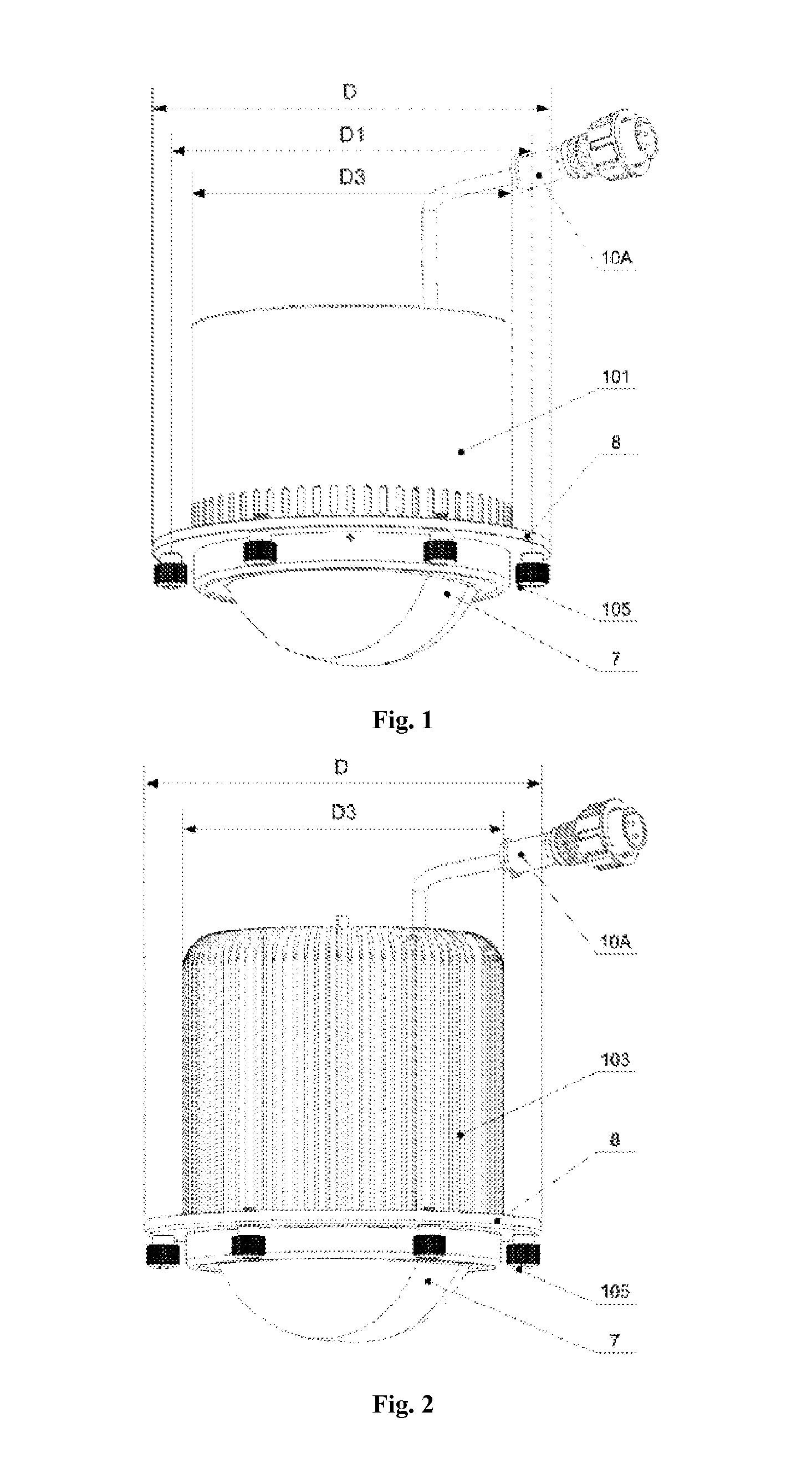
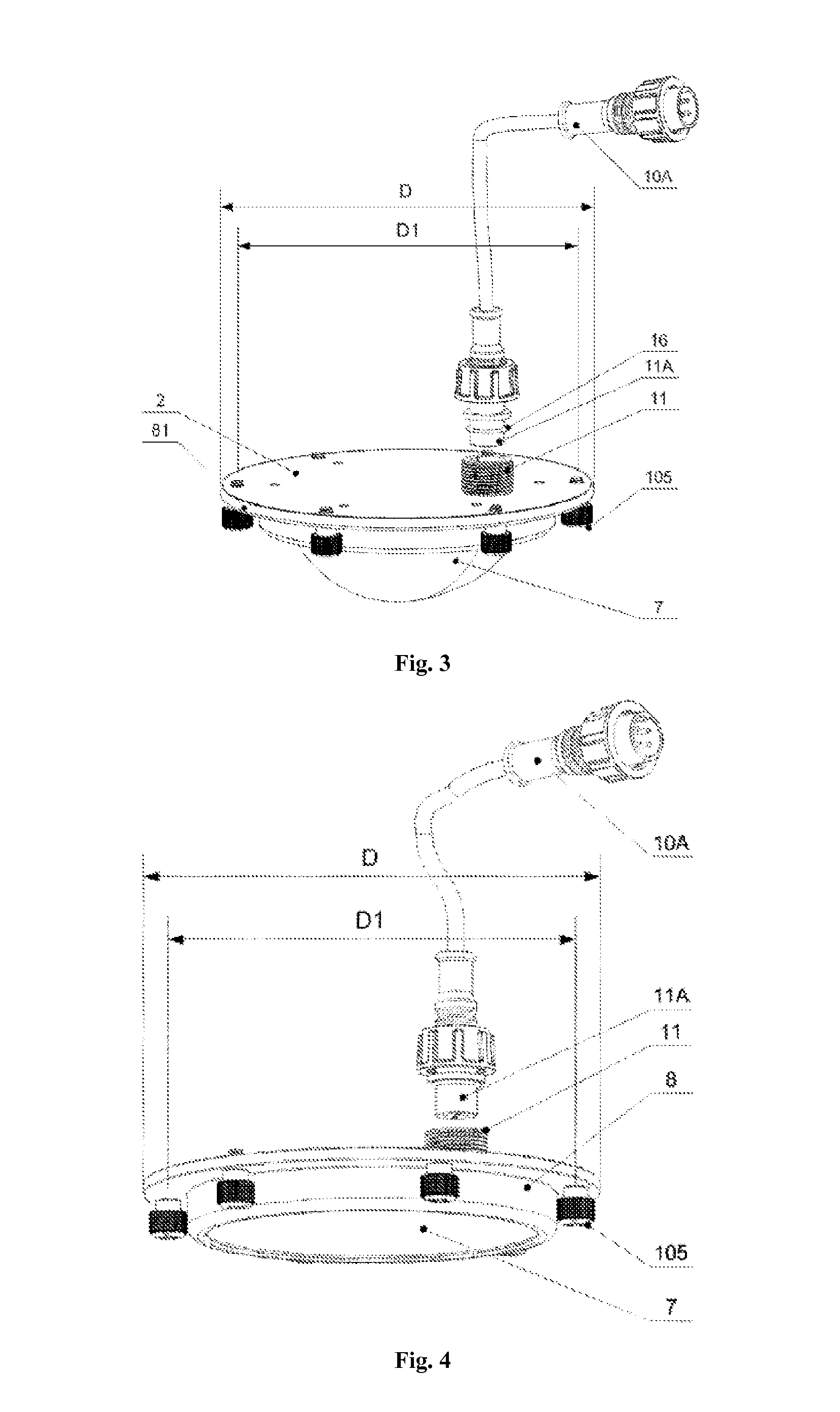
The present invention discloses a method for constructing a universal LED bulb, a flange snap ring type LED bulb and a lamp. A heat conductive bracket (3) with a flange is used as a structure supporting main body of the bulb to establish an optical engine core member of the LED bulb. An inner snap ring (81) fixed to the heat conductive bracket (3) is used to support the optical engine core member in an auxiliary manner. The optical engine core member is composed of the heat conductive bracket (3), an optical engine module (4), the inner snap ring (81), an inner cover (6), an electric connector (11) and a light distribution optical lens (7). The optical engine module (4) is made up of an optical engine die plate, an LED chip and a relevant wiring by bonding and packaging, or is further integrated with a power supply drive chip.

Description

FIELD OF THE INVENTION[0001]The present invention relates to a method for constructing a universal LED bulb, a flange inner snap ring type LED bulb and a lamp, which involves the field of LED lighting technology.BACKGROUND OF THE INVENTION[0002]As a new generation of lighting technology, LED semiconductor lighting has five energy-saving advantages incomparable by the existing other lighting technologies, such as high photoelectric conversion efficiency, easy control of light source direction, easy control of lighting time and manner, high light source color rendering property, and a high power factor under reasonable design, thus being warmly welcomed by worldwide investors and vigorously supported by the governments of all countries. The luminous efficiency of most current LED lamps may exceed 70 LM / W, thus having better energy saving advantages than the traditional energy saving lamps. The luminous efficiency of green LEDs may be up to 683 LM / W theoretically; the theoretical effic...

Claims


Application Information

Patent Timeline
Patent Type & Authority Applications(United States)
IPC IPC(8): F21V17/16F21V21/00F21V5/04F21V17/12F21V29/83F21V9/16F21V23/06F21V29/74F21S8/08F21V29/70F21V31/00
CPCF21V17/168F21V29/70F21V21/00F21V5/048F21V17/12F21V31/005F21W2131/103F21V23/06F21V29/74F21S8/085F21V29/83F21Y2101/02F21V9/16F21V21/28F21W2111/02F21S8/03F21Y2113/00F21K9/20F21K9/232F21Y2115/10Y10T29/49117F21V9/30F21S8/00
Inventor ZHANG, JIQIANGZHANG, ZHEYUAN
Owner GUIZHOU GUANGPUSEN PHOTOELECTRIC
Learn More