Probe assembly with rotary tip

a technology of rotary tip and probe, which is applied in the direction of electrical testing, measurement devices, instruments, etc., can solve the problems of reducing the operation rate of the inspection apparatus, reducing the reliability of inspection, and significantly difficult to remove only the thin oxide film, so as to reduce the damage to the pad and ensure the connection. reliable

Inactive Publication Date: 2008-09-11
KIMOTO GUNSEI
View PDF4 Cites 8 Cited by
  • Summary
  • Abstract
  • Description
  • Claims
  • Application Information

AI Technical Summary

Benefits of technology

[0023]Therefore, an object of the invention is to provide a probe which provides reliable electrical connection and is cleaning-free with a configuration that the oxide film is removed by precisely controlled rubbing operation with damage to the pad being minimized, and an adhesive material such as the removed oxide film is cleaned off the probe immediately before or after the inspection.

Problems solved by technology

Problems arising from the refined, narrow-pitched pad arrangement include that the probe structure should correspond to the precise pad arrangement to provide electrical conduction between the probe and the chip pad for electrical characteristics testing or circuit inspection of electronic devices.
Such a cleaning process may reduce operation rates of the inspection apparatus or decreases inspection reliability.
It is significantly difficult, however, to only remove the thin oxide film to expose the pad surface.
The rubbing operation abrades not only the oxide film but also the pad material deeply, and thus the pad surface may be damaged.
As a result, connection failure may be caused in a subsequent wire bonding process.
Electronic circuits formed in a lower part of the pad may also be damaged.
In addition, if the probe tip is left for a long time with debris of the abraded pad, such as aluminum, adhering to the probe tip, the adhering material may become oxidized and firmly adhere to the probe tip that cannot be removed at the subsequent rubbing operation for inspection.

Method used


Image

  • Probe assembly with rotary tip
  • Probe assembly with rotary tip
  • Probe assembly with rotary tip

Examples


first embodiment

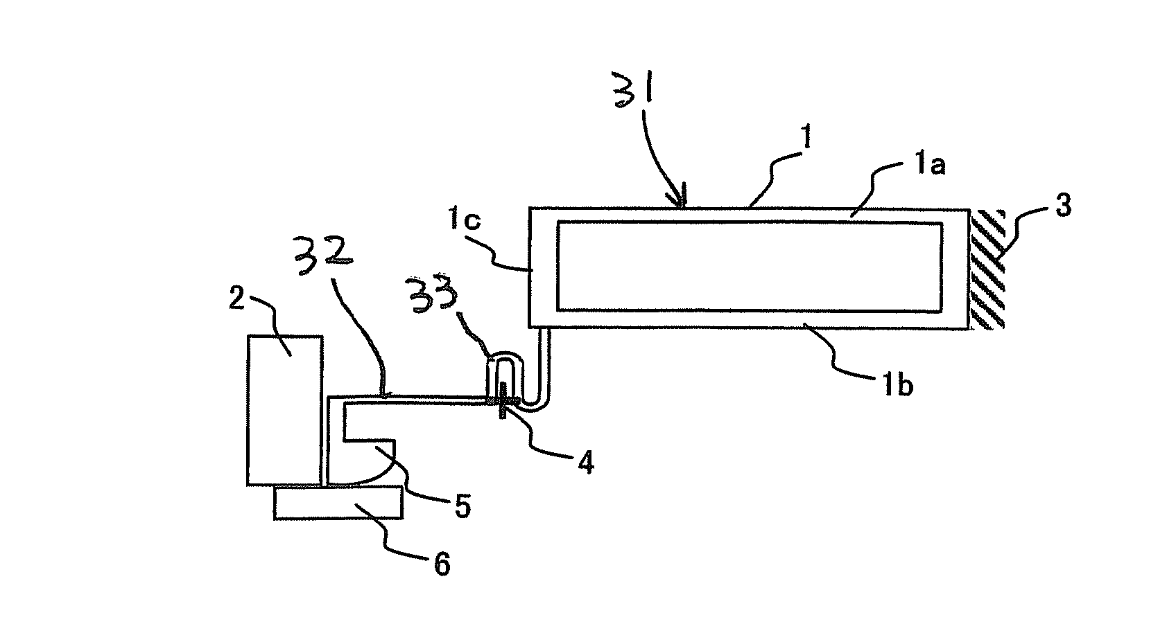
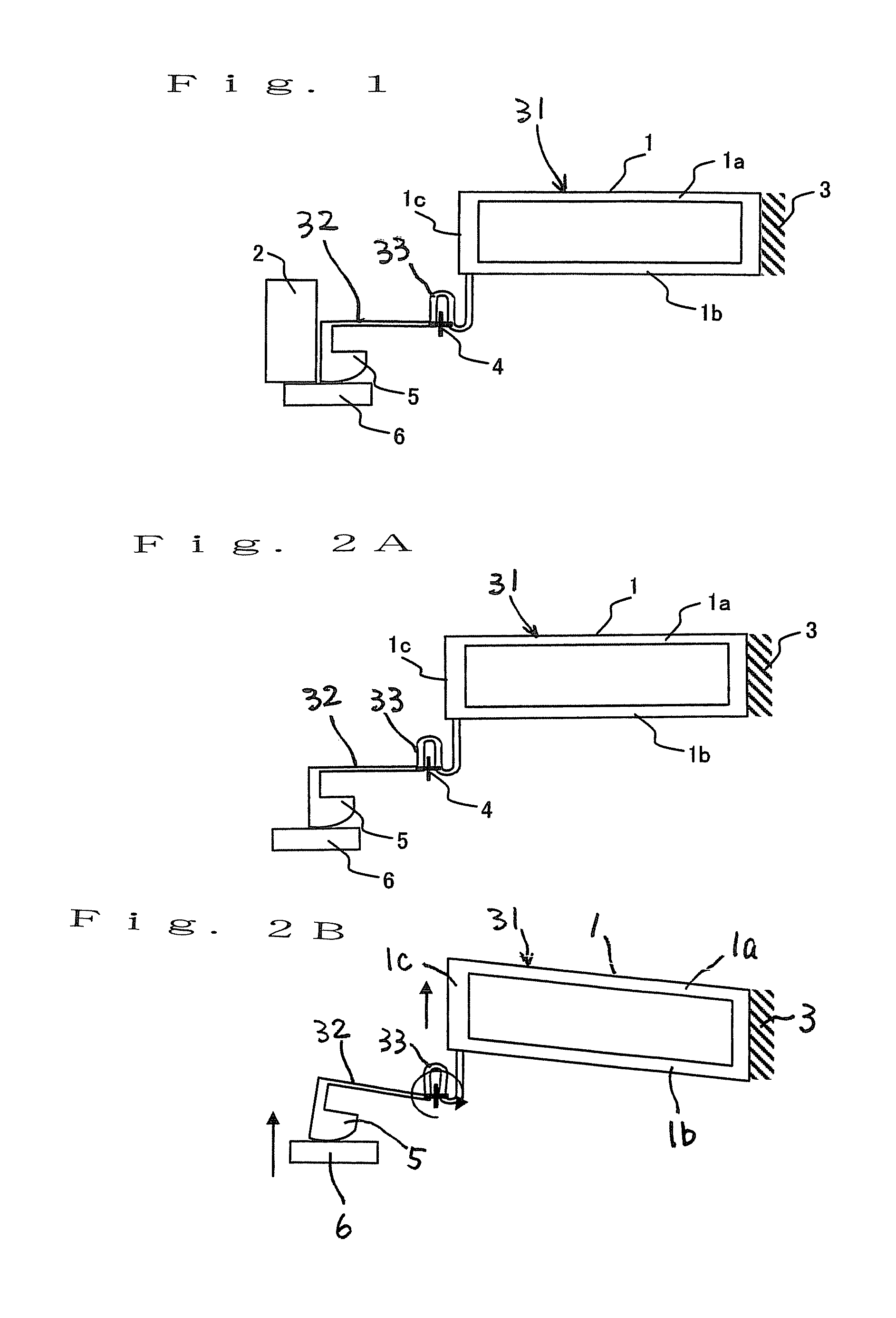
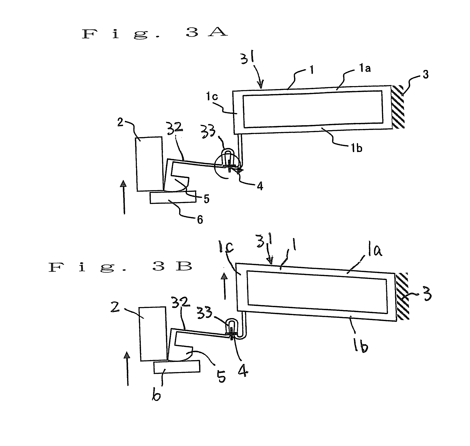
[0042]FIG. 1 is a side view of a probe assembly according to a first embodiment of the invention. FIGS. 2A, 2B, 3A and 3B are side views illustrating the general operation of the present probe.

[0043]As shown in FIG. 1, the probe has a link structure with a parallel spring 1. Upper and lower sides of the link structure are parallel beams 1a and 1b, respectively. An end of the link structure is formed as a vertical probe portion 1c, and a base end portion of the link structure is formed as a fixed end 3. These components altogether form a Z-deforming portion 31. A support arm 32 is provided to extend from the vertical probe portion 1c. The support arm 32 includes a tip contact element 5 at an end thereof, and a displacement absorbing portion 33 in a middle area thereof. In the example of FIG. 1, the displacement absorbing portion 33 is formed in an inverted U-shape, but it may alternatively be formed in a U-shape. When the tip contact element 5 is displaced (moved) vertically, the dis...

second embodiment

[0056]FIGS. 6A, 6B and 7 illustrate a probe assembly according to a second embodiment of the invention. FIGS. 8A to 8C illustrate operation of the present embodiment. In FIGS. 6A and 6B, a cleaning sheet 7 is disposed with a rough surface 7a contacting with the tip contact element 5. An exemplary structure of the cleaning sheet 7 is shown in FIG. 7, which may be obtained in the following manner. In a resin sheet, openings are provided through which probes are to be inserted. A cantilever cleaning sheet 71 is provided on one side of the opening. Fine particles such as diamond particles are applied to the surface of the cleaning sheet 7 where it abuts the tip contact element 5. The cleaning sheet 7 is disposed such that an end of the rough surface 7a abuts a portion of the tip contact element 5. As the tip contact element 5 rotates, the tip contact element 5 and the rough surface 7a are displaced relatively, and rub against each other.

[0057]Referring to FIGS. 8A to 8C, the operation o...

third embodiment

[0060]FIGS. 9A and 9B illustrate a tip contact element of a probe according to a third embodiment of the invention. The tip contact elements of the first and second embodiments may also be serrated as shown in FIGS. 9A and 9B. The serrated shape, in combination with a rigidity design, of the tip contact element promotes destroying the oxide film. With this structure, a more preferred rubbing amount may be determined.


PUM


Abstract

A probe which is cleaning-free, of which rubbing operation can be precisely controlled, and can be used for narrow-pitch pads, is provided. The probe assembly includes: a Z-deforming portion elastically deformable at least in a vertical direction; a tip contact element which includes a contact portion having a curved section, the tip contact element being connected to and supported on an end of the Z-deforming portion via an arm member, the contact portion being made to contact with an electrode pad and is vertically displaceable and rotatable; and a stopper for restricting movement of the tip contact element. After the tip contact element is rotated, due to pushing force from the electrode pad, for a certain distance in a direction of rotation, the stopper controls the movement of the tip contact element to prevent further rotation and to allow vertical movement.

Description

BACKGROUND OF THE INVENTION[0001]1. Field of the Invention[0002]The present invention relates to a probe assembly (a contact assembly) used for inspecting circuits on plural semiconductor chips formed on a wafer in a production process of an electronic device such as LSI. More particularly, the present invention relates to a probe assembly mounted on a probe card used for inspecting the circuits on a wafer basis. In the circuit inspection, probes, i.e., contacts, are made to contact with electrode pads arranged on a chip to provide electrical conduction collectively between the probes and the chips.[0003]2. Description of Prior Art[0004]As semiconductor technology advances, electronic devices have become more highly integrated, and electrode pads on each wafer chip have also increased in number. Pads have become more precisely arranged, whereby pad areas become smaller and pad pitches becomes narrow. Also, a chip size package (CSP) system becomes dominant in which a bear, non-packag...

Claims


Application Information

Patent Timeline
Patent Type & Authority Applications(United States)
IPC IPC(8): G01R1/067
CPCG01R1/06716G01R1/06738G01R1/06727G01R1/073
Inventor KIMOTO, GUNSEISAKUMA, TAKESHI
Owner KIMOTO GUNSEI
Why Eureka
Try Eureka