
Display apparatus and method of manufacturing the same

a technology of display apparatus and manufacturing method, which is applied in the direction of static indicating devices, non-linear optics, instruments, etc., can solve the problems of reducing and achieve the effect of increasing the adhesion and increasing the electrical connection reliability between the flexible substrate and the printed circuit board

Active Publication Date: 2017-03-09
SAMSUNG DISPLAY CO LTD
View PDF10 Cites 7 Cited by
  • Summary
  • Abstract
  • Description
  • Claims
  • Application Information

AI Technical Summary

Benefits of technology

The present invention provides a display apparatus with a flexible substrate that has improved electrical connection reliability with the printed circuit board. This is achieved by distributing stresses on the flexible substrate and increasing adhesion between the substrate and printed circuit board. Essentially, the invention increases the reliability of the electrical connection between the flexible substrate and printed circuit board.

Problems solved by technology

Electrical connection reliability between the flexible substrate and the printed circuit board may decrease.

Method used


Image

  • Display apparatus and method of manufacturing the same
  • Display apparatus and method of manufacturing the same
  • Display apparatus and method of manufacturing the same

Examples


Embodiment Construction

[0044]Exemplary embodiments of the present invention will be described in more detail below with reference to the accompanying drawings, in which exemplary embodiments are illustrated. Exemplary embodiments of the present invention may, however, be embodied in many different forms and should not be construed as limited to the embodiments set forth herein. Like reference numerals refer to like elements throughout the specification and drawings.

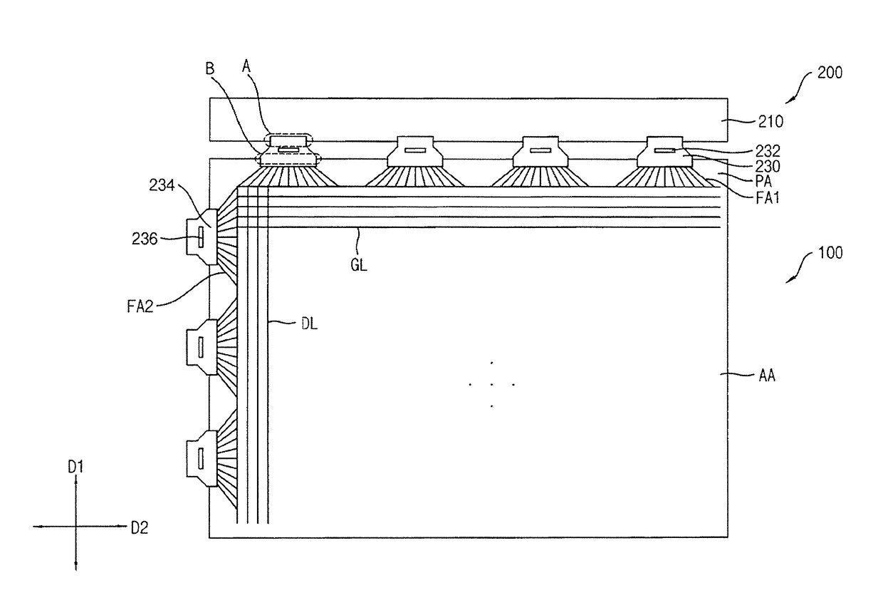
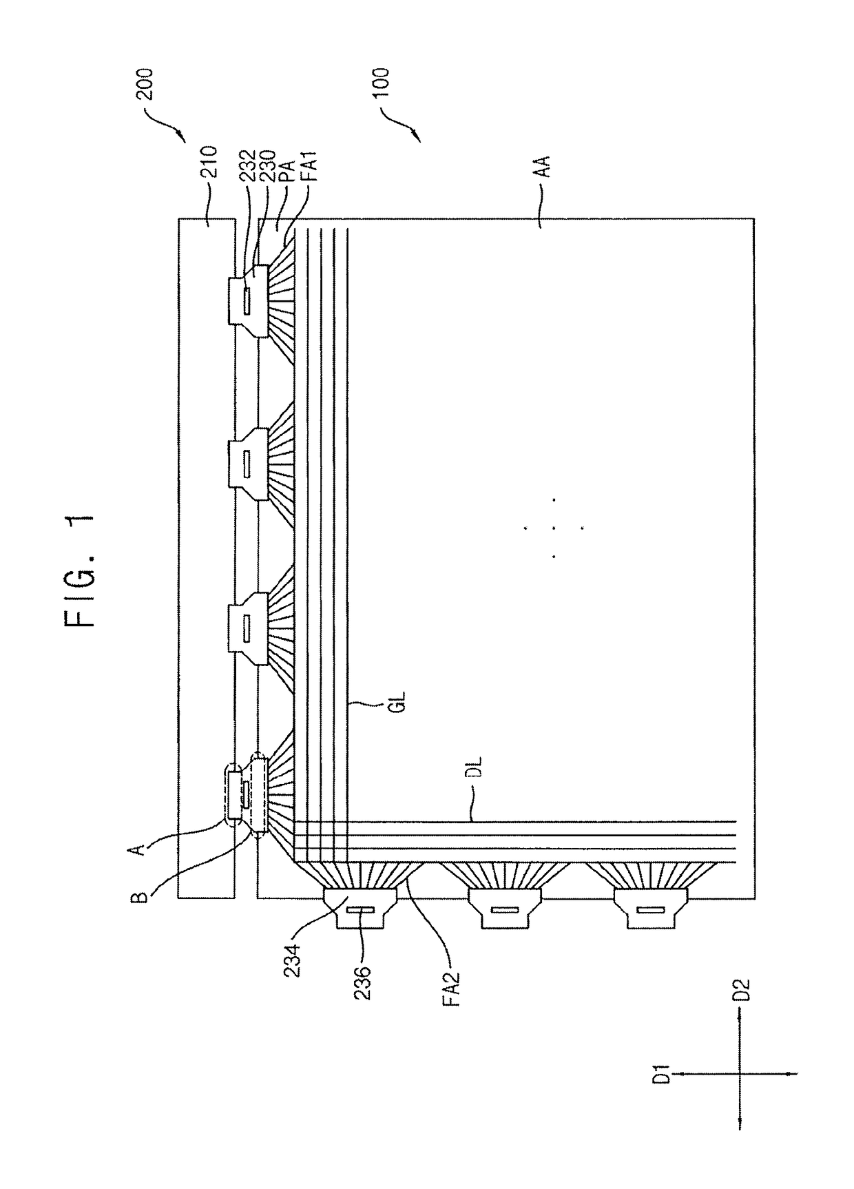
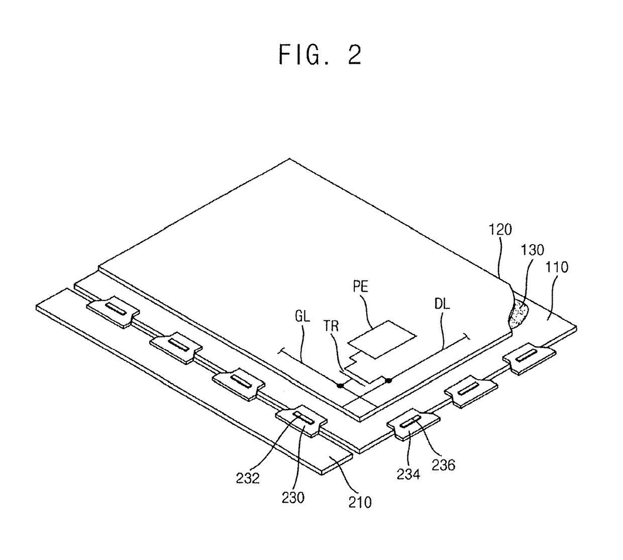
[0045]FIG. 1 is a plan view illustrating a display apparatus according to an exemplary embodiment of the present invention. FIG. 2 is a perspective view illustrating the display apparatus of FIG. 1. FIG. 3 is an enlarged view of region A of FIG. 1 illustrating a portion of the printed circuit board of FIG. 1. FIG. 4 is an enlarged view of region A of FIG. 1 illustrating a portion of the flexible substrate. FIG. 5 is an enlarged view of region B of FIG. 1 illustrating a portion of the display panel. FIG. 6 is an enlarged view of region B of FIG....


PUM


Abstract

A display apparatus includes a first substrate and a second substrate. The first substrate includes a switching element and a pixel electrode electrically connected to the switching element. A display panel driver applies a driving signal to the display panel. The display panel driver includes a printed circuit board including a first bonding pad and a flexible substrate electrically connecting the printed circuit board with the display panel. The flexible substrate includes a second bonding pad. The second bonding pad is electrically connected to the first bonding pad of the printed circuit board. The first bonding pad overlaps the second bonding pad. At least a portion of the first bonding pad and at least a portion of the second bonding pad extend in a direction which is at an acute angle with respect to a first direction parallel with a relatively longer side of the display panel.

Description

CROSS-REFERENCE TO RELATED APPLICATION[0001]This application claims priority under 35 USC §119 to Korean Patent Application No. 10-2015-0126291, filed on Sep. 7, 2015 in the Korean Intellectual Property Office (KIPO), the disclosure of which is incorporated by reference herein in its entirety.1. TECHNICAL FIELD[0002]Exemplary embodiments of the present invention relate to a display apparatus. More particularly, exemplary embodiments of the present invention relate to a method of manufacturing the display apparatus.2. DISCUSSION OF RELATED ART[0003]A display apparatus may include a display panel and a display panel driver. The display panel driver may include a printed circuit board and a flexible substrate which may connect the printed circuit board with the display panel electrically.[0004]A driving chip of the display panel driver may be disposed on a peripheral region of the display panel in a COG (chip on glass) configuration. The driving chip of the display panel driver may be ...

Claims


Application Information

Patent Timeline
Patent Type & Authority Applications(United States)
IPC IPC(8): G09G3/20
CPCG09G3/2092G09G2300/08G09G2310/0202G09G2310/0278G09G2300/0426G02F1/13452G09G3/3648G02F1/1333
Inventor JANG, SE-HUILEE, CHONG-GUKMOH, SANG-MOONMOON, SU-MI
Owner SAMSUNG DISPLAY CO LTD
Learn More