Socket for electrical conduit locknuts

a technology for electrical conduits and sockets, which is applied in the field of sockets, can solve the problems of difficult to estimate the torque applied to the locknut, insufficient tightening, and manual manipulation of the locknut, and achieve the effect of reducing manufacturing costs, facilitating machined, and simplifying the locknu

Inactive Publication Date: 2009-12-31
ALLRED DOUGLAS R +1
View PDF17 Cites 2 Cited by
  • Summary
  • Abstract
  • Description
  • Claims
  • Application Information

AI Technical Summary

Benefits of technology

[0015]The present invention provides a socket wrench for electrical locknuts that is highly tolerant of size differences of electrical locknuts of a nominal size and the number and spacing of lugs thereon. The socket wrench, in its most simple form, is machined from a single piece of metal, and includes a cylindrical wall that is unitary with a socket ceiling having a square drive aperture centered therein. A pair of diametrically-opposed semi-cylindrical vertical projections extend inwardly from the cylindrical wall. The vertical projections operate on a pair of diametrically-opposed lugs on the electrical locknut. The semi-cylindrical shape of the vertical projections causes the socket to self-center on an engaged locknut when the socket is turned in either clockwise or counterclockwise direction. Thus, a socket designed for a nominal size of electrical locknut is able to accommodate virtually any electrical locknut of that nominal size which incorporates multiple pairs of diametrically-opposed lugs. Although locknuts with uneven numbers of lugs are either extremely rare or nonexistent, it is likely that the socket could also successfully engage such a locknut.
[0016]In order to simplify and reduce the cost of manufacture, the electrical locknut socket wrench can be made of three pieces which are either assembled in a pressed fit, welded, or adhesively bonded together. A thickened cylindrical wall is used that is also unitary with a socket ceiling having a square drive aperture centered therein. An inner annular shoulder is cut in the thickened cylindrical wall, and diametrically-opposed holes are drilled parallel to the axis of the cylindrical wall. Cylindrical pins are then installed within the diametrically-opposed holes, so that semi-cylindrical vertical projections, extending from the shoulder to the bottom edge of the cylindrical wall, are formed. The cylindrical pins are either maintained in position by an interference fit, by welding, brazing or adhesive bonding.
[0017]For an alternative embodiment, the semi-cylindrical vertical projections are replaced by a pair of diametrically-opposed angular vertical projections, with the surface of each projection being formed by two intersecting planes. For a socket which is machined from a single piece of metal, the angular vertical projections are more easily machined.

Problems solved by technology

This method of manipulating a locknut has several problems.
First, it is difficult to estimate the torque being applied to the locknut, which may result either in it not being adequately tightened, or over-tightened so that the threads on the locknut and / or the threaded male stud end are stripped.
Secondly, the use of a screwdriver as a punch is ill-advised, as the worker may injure himself or damage equipment if the screwdriver slips off the lug of the locknut.
A major problem in designing a wrench for electrical locknuts is that there is little standardization in the shape and configuration of the locknuts.
As if that were not enough, the size of lugs on a single locknut may not be uniform.
These factors make it difficult to design a socket wrench which fits all locknuts of a particular inside diameter.

Method used


Image

  • Socket for electrical conduit locknuts
  • Socket for electrical conduit locknuts
  • Socket for electrical conduit locknuts

Examples


Embodiment Construction

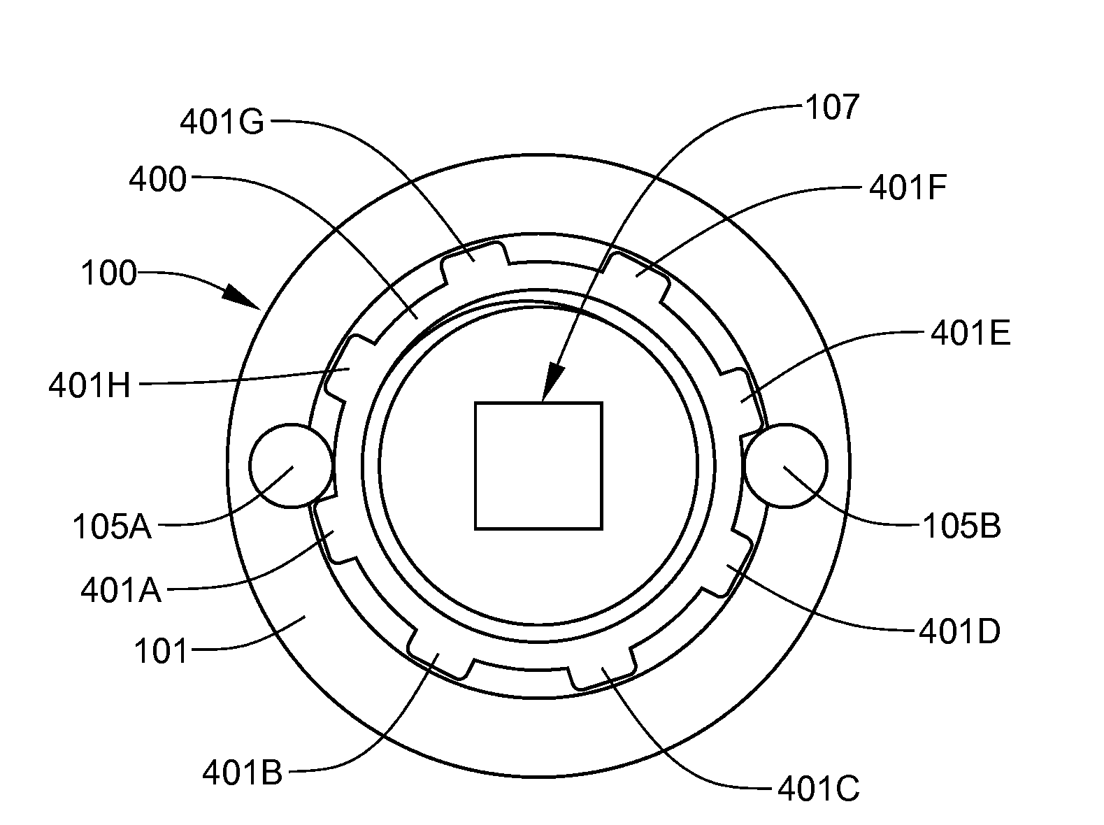
[0030]The present invention provides a socket wrench for electrical locknuts that is highly tolerant of size differences of electrical locknuts of a nominal size and the number and spacing of lugs thereon.

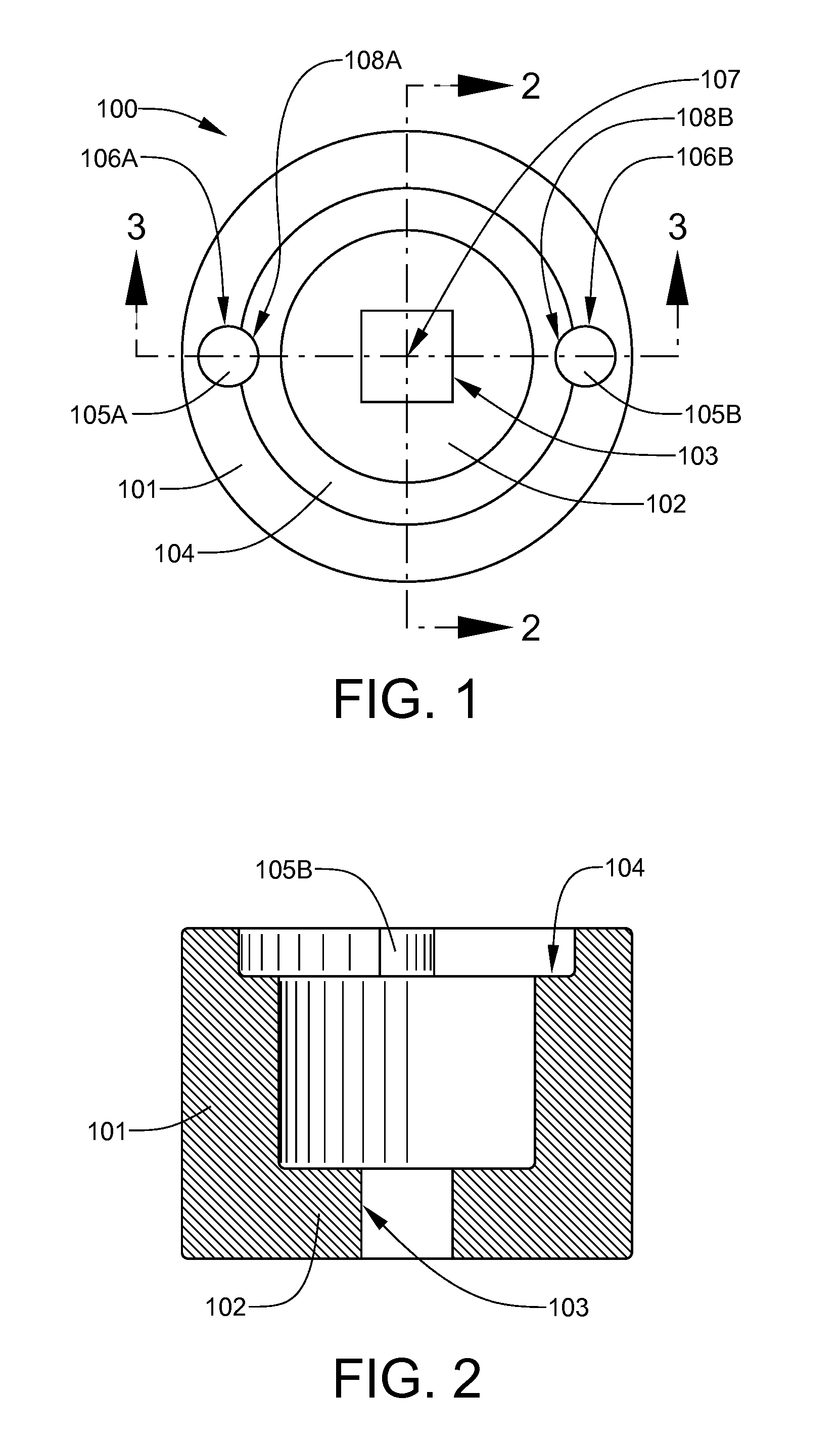
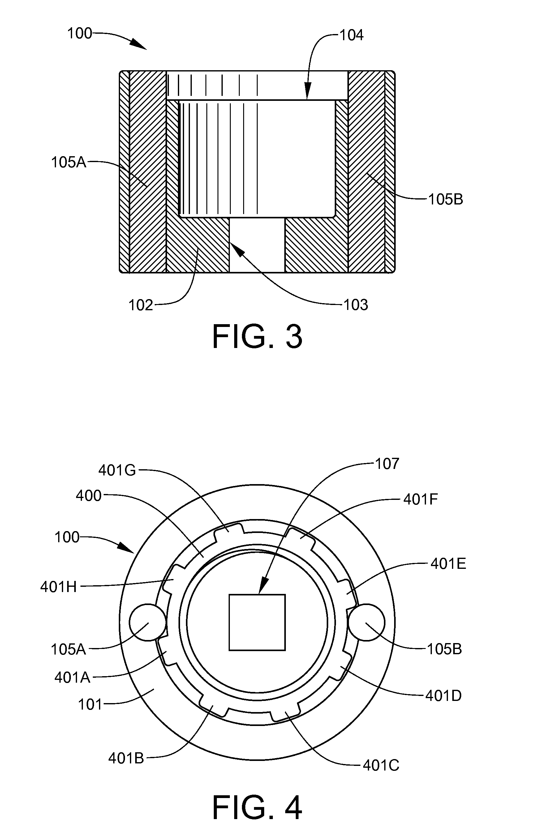
[0031]Referring now to FIG. 1, a first embodiment socket wrench 100 for electrical locknuts is seen in a bottom view. The first embodiment socket wrench 100 is assembled from three separate pieces which are joined together. A thickened cylindrical wall 101 is used that is also unitary with a socket ceiling 102 having a square drive aperture 103 centered therein. An inner annular shoulder 104 is cut in the thickened cylindrical wall 101, and identical cylindrical pins 105A and 105B are installed in diametrically-opposed holes 106A and 106B, respectively, which are drilled parallel to the axis 107 of the cylindrical wall 101. The cylindrical pins 105A and 105B are then installed within the diametrically-opposed holes 106A and 106B, respectively, so that semi-cylindrical vertical proj...


PUM


Abstract

The present invention provides a socket wrench for electrical locknuts that is highly tolerant of size differences of electrical locknuts of a nominal size and the number and spacing of lugs thereon. The socket wrench, in its most simple form, is machined from a single piece of metal, and includes a cylindrical wall that is unitary with a socket ceiling having a square drive aperture centered therein. A pair of diametrically-opposed semi-cylindrical vertical projections extend inwardly from the cylindrical wall. The vertical projections operate on a pair of diametrically-opposed lugs on the electrical locknut. The semi-cylindrical shape of the vertical projections causes the socket to self-center on an engaged locknut when the socket is turned in either clockwise or counterclockwise direction.

Description

[0001]This application has a priority date based on the filing of provisional patent application 61 / 073,363, which was filed on Jun. 17, 2008.FIELD OF THE INVENTION[0002]The present invention generally relates to sockets and, more specifically, to sockets for use with electrical conduit locknuts.BACKGROUND OF THE INVENTION[0003]Electro-metallic tubing, or EMT as it is commonly known, is thin-walled steel conduit that is commonly employed to encase conductors for electric circuits. EMT ranges in diameter from ½-inch to 4 inches. In order to secure the ends of EMT runs to switch, outlet, and connection boxes, a threaded male stub end fitting is slipped over and secured to the end of the tubing with either one or more set screws or a threaded compression nut. The threaded male stub end is then inserted through a knock-out in the switch, outlet or connection box, and subsequently secured to the box with a locknut having a plurality of peripheral tightening lugs. During assembly or disas...

Claims


Application Information

Patent Timeline
Patent Type & Authority Applications(United States)
IPC IPC(8): B25B13/50B25B13/06
CPCB25B13/50B25B13/065
Inventor ALLRED, DOUGLAS R.SWEAT, SHAWN J.
Owner ALLRED DOUGLAS R
Why Eureka
Try Eureka