Cutting Methods and Cutting Apparatus

a cutting apparatus and cutting method technology, applied in band saws, saw chains, manufacturing tools, etc., can solve the problems of wire saws that are difficult to cut workpieces in complicated shapes, the direction of processing force that occurs due to cutting changes, and the inability to cut workpieces

Active Publication Date: 2009-12-31
KOMATSU NTC LTD
View PDF6 Cites 27 Cited by
  • Summary
  • Abstract
  • Description
  • Claims
  • Application Information

AI Technical Summary

Benefits of technology

[0033]The other cutting apparatus of the present invention includes a cutting arm that extends a cutting wire such that it is capable of traveling, a fixed rotation mechanism, an X-Y moving mechanism, and control means. When a workpiece is cut, the X-Y moving mechanism is controlled such that a center of rotation of the cutting arm matches a real cutting position where the wire always contacts the workpiece, even if the cutting direction is changed, cutting processing can be precisely performed without abnormality at the position where the cutting directio

Problems solved by technology

However, if a wire saw tries to cut a workpiece in a complicated shape such as a free curved surface, the direction of processing force that occurs due to cutting changes.
As a result, the wire may be disengaged from the respective grooves of the grooved guide rollers or the wire may be broken.
Thus, there is a problem that wire saws are difficult to cut workpieces in complicated shapes.
Among them, jig sawing has hardly been used for precise cutting because of drawbacks of which processing force is large, burring tends to occur due to rough cutting s

Method used


Image

  • Cutting Methods and Cutting Apparatus
  • Cutting Methods and Cutting Apparatus
  • Cutting Methods and Cutting Apparatus

Examples


first embodiment

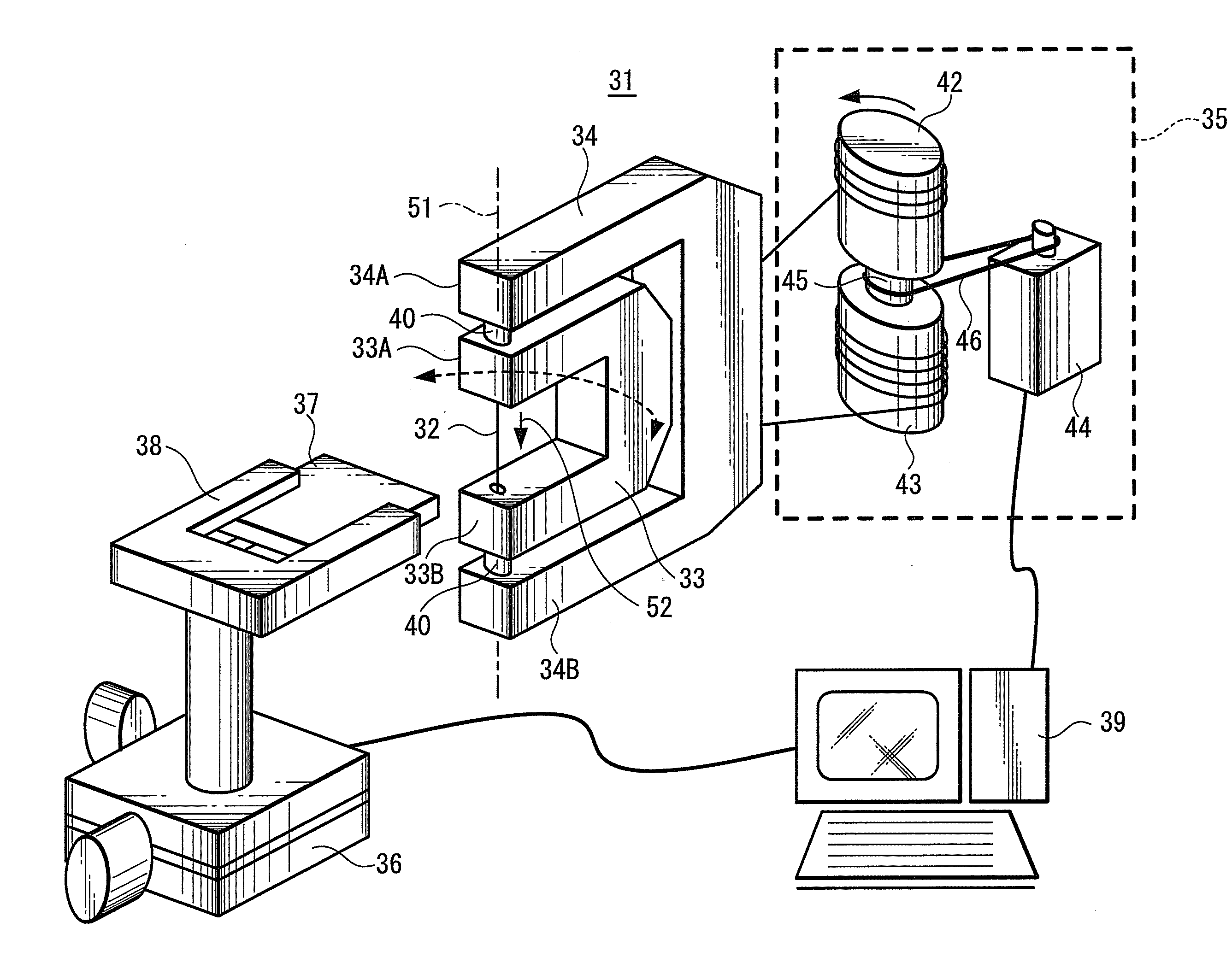
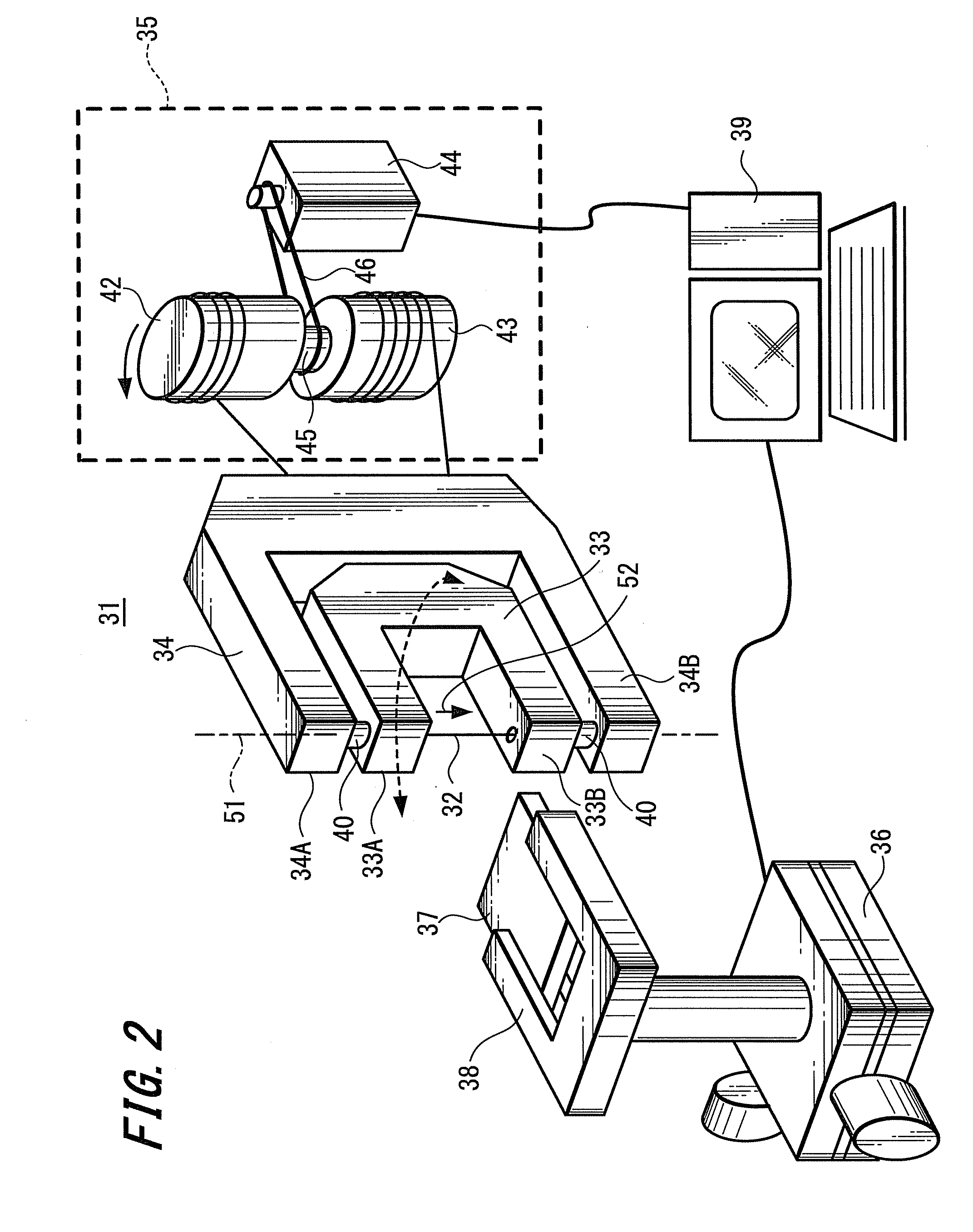
[0055]FIG. 2 shows an outlined structure of a cutting apparatus that uses the cutting method according to the present invention. A cutting apparatus 31 according to this embodiment includes a cutting arm 33 having a cutting wire 32; and a rotation mechanism 34 that rotates the cutting arm 33 around a center axis 51 of the wire 32. In addition, the cutting apparatus 31 includes a wire supply / collection unit 35; an orthogonal three-axis moving table 36 having one axis of a wire travelling direction 52 of a cutting portion of a workpiece 37; a chucking device 38 holding the workpiece 37 integrally supported on the moving table 36; and a control means, for example, a computer 39, that issues commands to the wire supply / collection unit 35, the rotation mechanism 34, and the moving table 36.

[0056]As shown in FIG. 3, the cutting arm 33 is formed, for example, in a “]” letter shape (one-shorter-side-open rectangular shape). Disposed on the respective distal sides of upper and lower arm sect...

second embodiment

[0073]In addition to the operation of the cutting apparatus 61 the cutting method thereof will be described. Before cutting processing is performed, the wire's center axis 62 of the cutting arm 63 is matched with the center of rotation of the rotation table 71. In other words, the cutting arm 63 is aligned through the X-Y table 72 such that the wire's center axis 62 of the cutting wire 63 vertically extended between the grooved guide rollers 64 and 65 on the distal side of the cutting arm 63 matches the center of rotation of the rotation table 71. This alignment may be performed manually by operating the X-Y table 72 or the X-Y table 68 may be automatically aligned according to a command received from the computer 39. In this state, the cutting wire 32 is traveled according to a command received from the computer 39. In addition, according to a command received from the computer 39, the moving table 36 is driven, the cutting portion of the workpiece 37 is moved to the center of the...

third embodiment

[0076]Next, a cutting method and a cutting apparatus which can more precisely perform cutting processing, will be described.

[0077]Next, the state of the wire 32 that actually performs cutting processing will be examined, for example, using the cutting apparatus 61 shown in FIG. 4. As shown in FIG. 6, when cutting processing is performed, a position 69 at which the wire 32 contacts and substantially cuts the workpiece 37 (hereinafter, this position is referred to as the real cutting position of the wire) is behind the wire's center axis 62 of the wire extended vertically between both the foregoing grooved guide rollers 64 and 65. In other words, since the wire 32 presses the workpiece 37 with a required processing force, the wire 32 bends in a bow shape due to its reaction. Thus, the real cutting position 69 of the wire 32 moves with a delay of a distance δ from the wire's center axis 62. In this state, if the cutting direction is changed and the cutting arm 63 is correspondingly ro...


PUM

PropertyMeasurementUnit
Stiffnessaaaaaaaaaa
Tensionaaaaaaaaaa

Abstract

The present invention provides cutting methods and cutting apparatus that can precisely cut workpieces in complicated shapes with high aspect ratios regardless of materials of the workpieces. The present invention is cutting methods and cutting apparatus using a wire saw wherein cutting processing is performed for a workpiece by extending a cutting wire on a cutting arm that rotates around a wire's center axis or a real cutting position relative to a fixed section and rotating the cutting arm such that a cutting direction of the wire matches a support direction of a total stiffness that supports the wire.

Description

RELATED APPLICATION DATA[0001]The present application claims the priority benefit of, Japanese Patent Application JP P2006-182387 filed on Jun. 30, 2006 and Japanese PCT / JP2007 / 62923 filed on Jun. 27, 2007.TECHNICAL FIELD[0002]The present invention relates to cutting methods and cutting apparatus for workpieces. In particular, the present invention relates to cutting methods and cutting apparatus using a wire, a so-called wire saw, that cuts workpieces in complicated shapes.BACKGROUND ART[0003]FIG. 13 shows an outlined structure of a cutting method for workpieces using a conventional wire saw. As shown in FIG. 13, in a conventional wire saw, a workpiece cutting wire 2 supplied from a wire supply / collection unit (not shown) is wound in coil shapes around a plurality of grooved rollers 3 (3A, 3B, 3C) and then collected to the wire supply / collection unit. When a workpiece 4 such as silicon ingot or crystal is cut, while slurry abrasive solution 5 containing lapping oil and free abrasiv...

Claims


Application Information

Patent Timeline
IPC IPC(8): B26D1/46
CPCB23D57/0007B28D5/045B23D57/0053B23D57/0038Y10T83/7264Y10T83/7076Y10T83/9292Y10T83/04
Inventor YAZAWA, TAKANORIISHIKAWA, KEIICHIMINETA, KOU
Owner KOMATSU NTC LTD
Why Eureka
Try Eureka