
Structures for securing containers

a technology for structures and containers, applied in the field of structures for securing containers, can solve the problems of large leakage from the system, difficult recycling, and high cost of replacement, and achieve the effects of cost-effective production or replacement, increased durability of containers, and recyclables

Inactive Publication Date: 2009-12-31
RAND WHITNEY GROUP
View PDF54 Cites 2 Cited by
  • Summary
  • Abstract
  • Description
  • Claims
  • Application Information

AI Technical Summary

Benefits of technology

[0003]The present invention relates to structures for securing containers. The structures disclosed in the present invention, when embodied in containers, can increase the durability of the containers while keeping the containers cost-efficient to produce or replace, and / or recyclable.
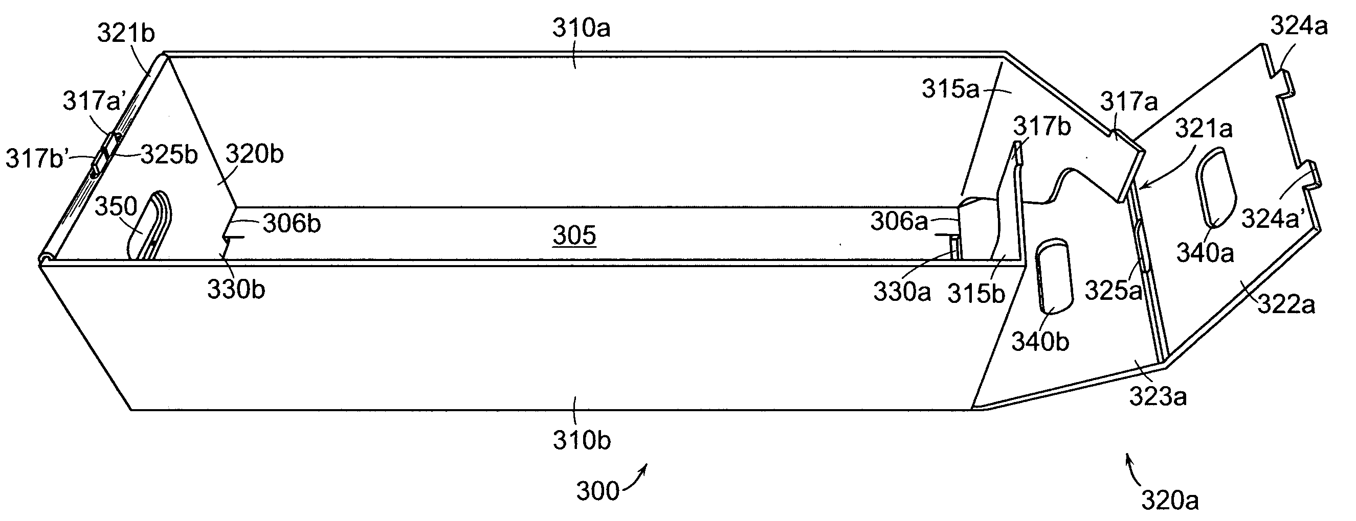
[0005]According to one embodiment of the present invention, for a given end element, a slot can be cut in the end element near or bordering one or more of the transverse scores of the end element. The long axis of the slot can be parallel to the one or more of the transverse scores. One or more of the end flaps can have an extension. The extension can be insertable into one of the slots when the fold-over leaf is folded over the end flaps, to prevent an outward lateral movement of the end flap along the long axis of the slot with respect to the container. The extension can be located at least partially above the hand hole when the fold-over leaf is folded over the end flaps in spaced parallelism to the other leaf. Two or more extensions may be inserted into one slot side by side along the long axis of the slot.

Problems solved by technology

This tray, while having been an effective product for years, is now viewed as costly to replace, a source of great leakage from their system (e.g., people take them home for personal use), and difficult to recycle.
One of the reasons that the corrugated trays were replaced by the plastic trays was that the corrugated paper trays were not as durable as the plastic trays.

Method used


Image

  • Structures for securing containers
  • Structures for securing containers
  • Structures for securing containers

Examples


Embodiment Construction

[0018]A description of example embodiments of the invention follows.

[0019]The present invention relates to structures for securing containers.

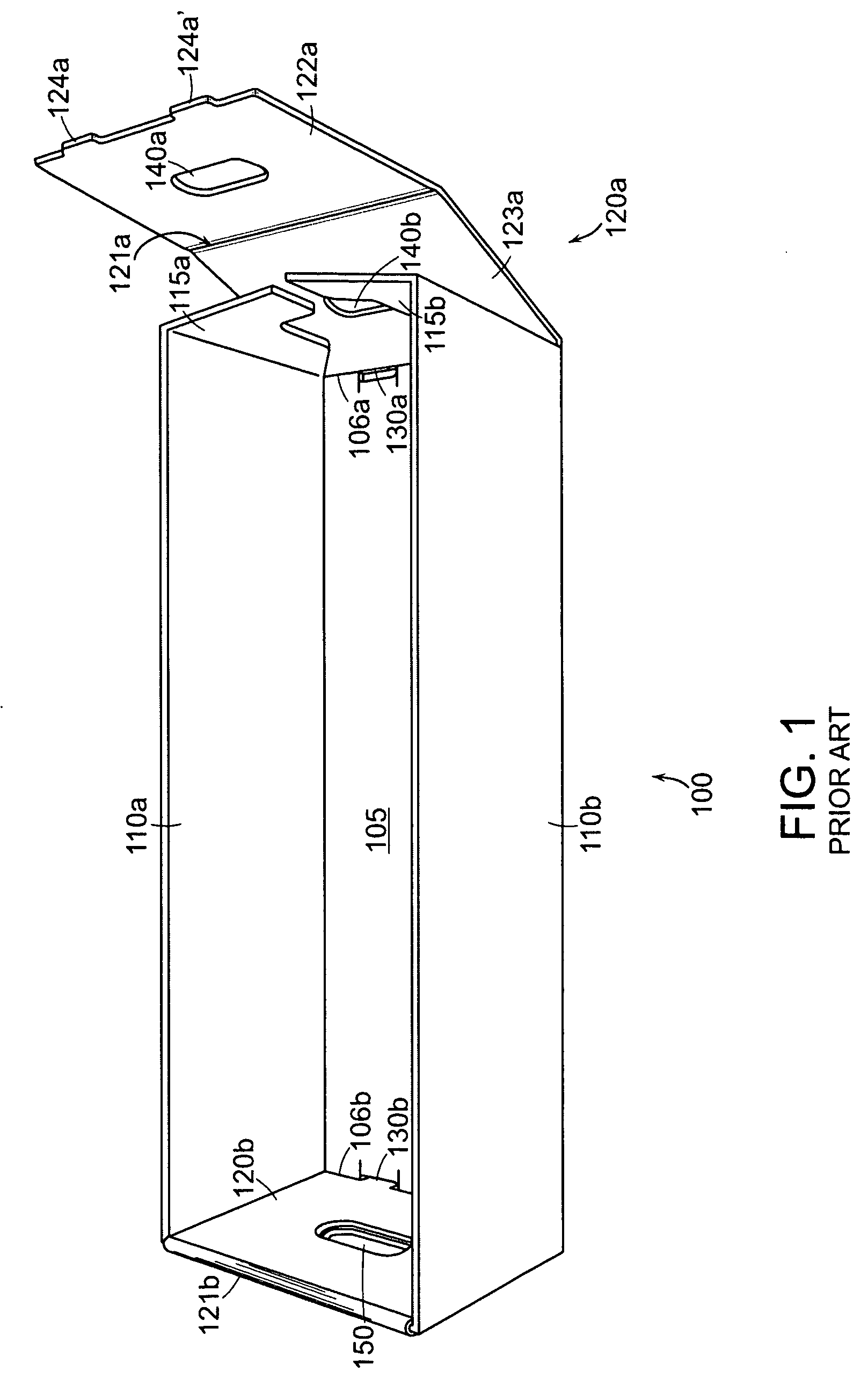
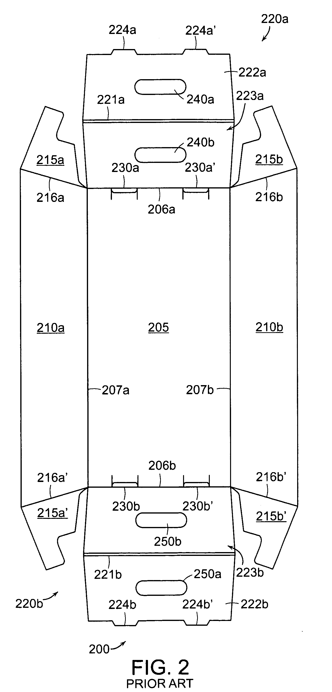
[0020]FIG. 1 is a perspective view of a corrugated paper letter tray that was previously used by the USPS. The assembled tray 100 has a bottom 105, two sides 110a and 110b, and two folded end elements 120a and 120b. One end element 120a is partially unfolded to show the structures it comprises. Each side has two end flaps folded therefrom. Only one end flap of each side is shown in FIG. 1 (end flap 115a folded from side 110a and end flap 115b folded from side 110b). Each end element folds from the bottom along a folding line (shown in FIG. 1 as 106a and 106b for end elements 120a and 120b, respectively) and has a pair of parallel transverse scores close to each other (each pair shown in FIG. 1 as 121a and 121b for end elements 120a and 120b, respectively) to define two leaves (shown in FIG. 1 as 122a and 123a for end element 120a) and permit o...


PUM


Abstract

Disclosed herein are improvements to fold-over structures in containers comprising two leaves foldably connected to each other along a folding line and a flap sandwiched by the two leaves when they fold together. A slot can be cut along the folding line and the flap can have an extension that is insertable into the slot to prevent the lateral movement of the flap along the long axis of the slot. One leaf can have a locking tab insertable into a slit cut in the container when the two leaves fold together in spaced parallelism to each other. An outer edge of the locking tab can extend beyond the corresponding end of the slit to secure the locking tab once inserted into the slit. The container can have a hand hole cut through both leaves and in alignment with the flap at least along the upper edge of the hand hole.

Description

RELATED APPLICATION[0001]This application is a continuation-in-part of U.S. application Ser. No. 12 / 164,728, filed Jun. 30, 2008. The entire teachings of the above application is incorporated herein by reference.BACKGROUND OF THE INVENTION[0002]Containers exist in many forms, e.g., cartons, boxes, crates, cans, buckets, trays, etc. The United States Postal Service (USPS) currently uses a polyethylene letter tray in its Processing and Distribution Centers nationwide to convey sorted letter mail. This tray, while having been an effective product for years, is now viewed as costly to replace, a source of great leakage from their system (e.g., people take them home for personal use), and difficult to recycle. Prior to the plastic trays, the USPS used corrugated letter trays to convey sorted letter mail. One of the reasons that the corrugated trays were replaced by the plastic trays was that the corrugated paper trays were not as durable as the plastic trays. There is a need for a contai...

Claims


Application Information

Patent Timeline
Patent Type & Authority Applications(United States)
IPC IPC(8): B26D5/42
CPCB65D5/22
Inventor MINTON, RICHARDSTUHMER, STEVEN T.
Owner RAND WHITNEY GROUP
Learn More