
Self-Calibration Circuit With Gyrated Output Impedance

a self-calibration circuit and output impedance technology, applied in the field of instrumentation, can solve the problems of performance oscilloscopes, large uncertainty and measurement errors, and achieve the effect of not degrading the rf performance of the oscilloscop

Active Publication Date: 2009-12-31
NATIONAL INSTRUMENTS
View PDF15 Cites 11 Cited by
  • Summary
  • Abstract
  • Description
  • Claims
  • Application Information

AI Technical Summary

Benefits of technology

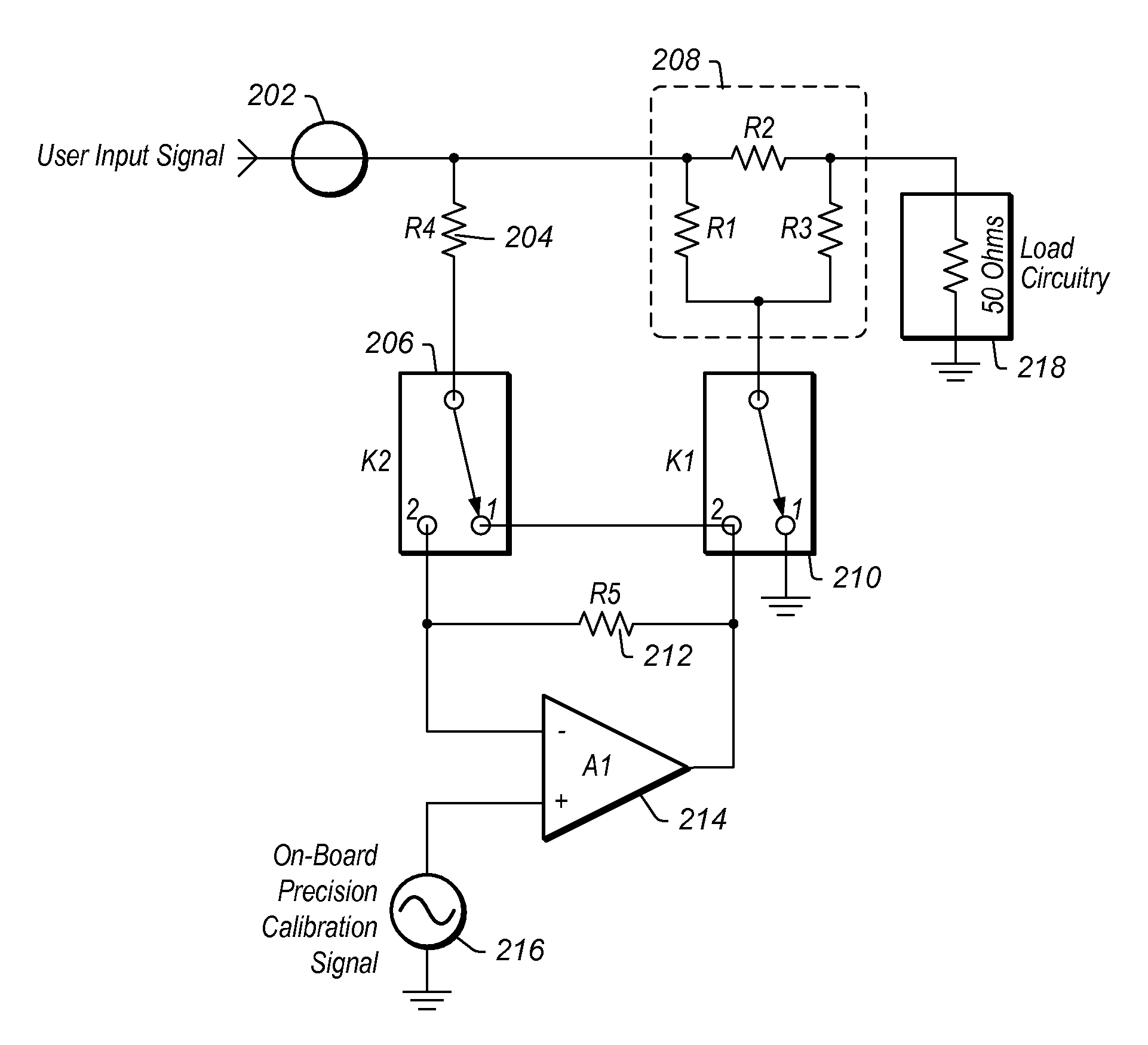
[0009]Various embodiments of the invention comprise a self-calibration circuit configured to provide self-calibration functionality for various instruments and / or measurement devices, such as an oscilloscope, by generating and providing an internal precision calibration signal without degrading the RF performance of the oscilloscope. Embodiments of the self-calibration circuit may eliminate the need for using higher power, complex, or custom methods of self-calibration. The self-calibration circuit may be configured to implement an impedance transformation technique where active and passive circuit elements with carefully chosen values are configured in an impedance converter. During self-calibration, switching elements comprised in the self-calibration circuit may be toggled to create a servo loop within the circuit, comprising an amplifier, with an attenuator and resistive component acting as feedback elements. The circuit may hence become an impedance gyrator and behave as a precision source having an output impedance that matches the impedance of the load.
[0013]A measurement system may be configured with the capability to self-calibrate. The system may include an attenuator with a first terminal configured to receive a user input signal and a second terminal configured to couple to a load, and an amplifier having a first input configured to receive a calibration signal. A first switching element may be configured with two selectable switching configurations, with the first switching configuration coupling the first terminal of the attenuator to a second input of the amplifier, and the second switching configuration coupling the first terminal of the attenuator to an output of the amplifier. A second switching element may also be configured with two selectable switching configurations, with the first switching configuration coupling a third terminal of the attenuator to the output of the amplifier, and the second switching configuration coupling the third terminal of the attenuator to reference ground. A combination of the first switching configuration for the first switching element and the first switching configuration for the second switching element may establish a servo loop that comprises the amplifier, and the attenuator as a feedback element, with the servo loop operating as a precision signal source having an output impedance that matches an impedance of the load, to deliver the calibration signal to the load.

Problems solved by technology

As time progresses, or as the surrounding temperature varies, changes in component values can easily result in greater uncertainty and measurement errors.
A problem arises in high performance oscilloscopes, and in particular RF (radio frequency) oscilloscopes, regarding the location and mechanism whereby to internally provide a precision calibration signal.

Method used


Image

  • Self-Calibration Circuit With Gyrated Output Impedance
  • Self-Calibration Circuit With Gyrated Output Impedance
  • Self-Calibration Circuit With Gyrated Output Impedance

Examples


Embodiment Construction

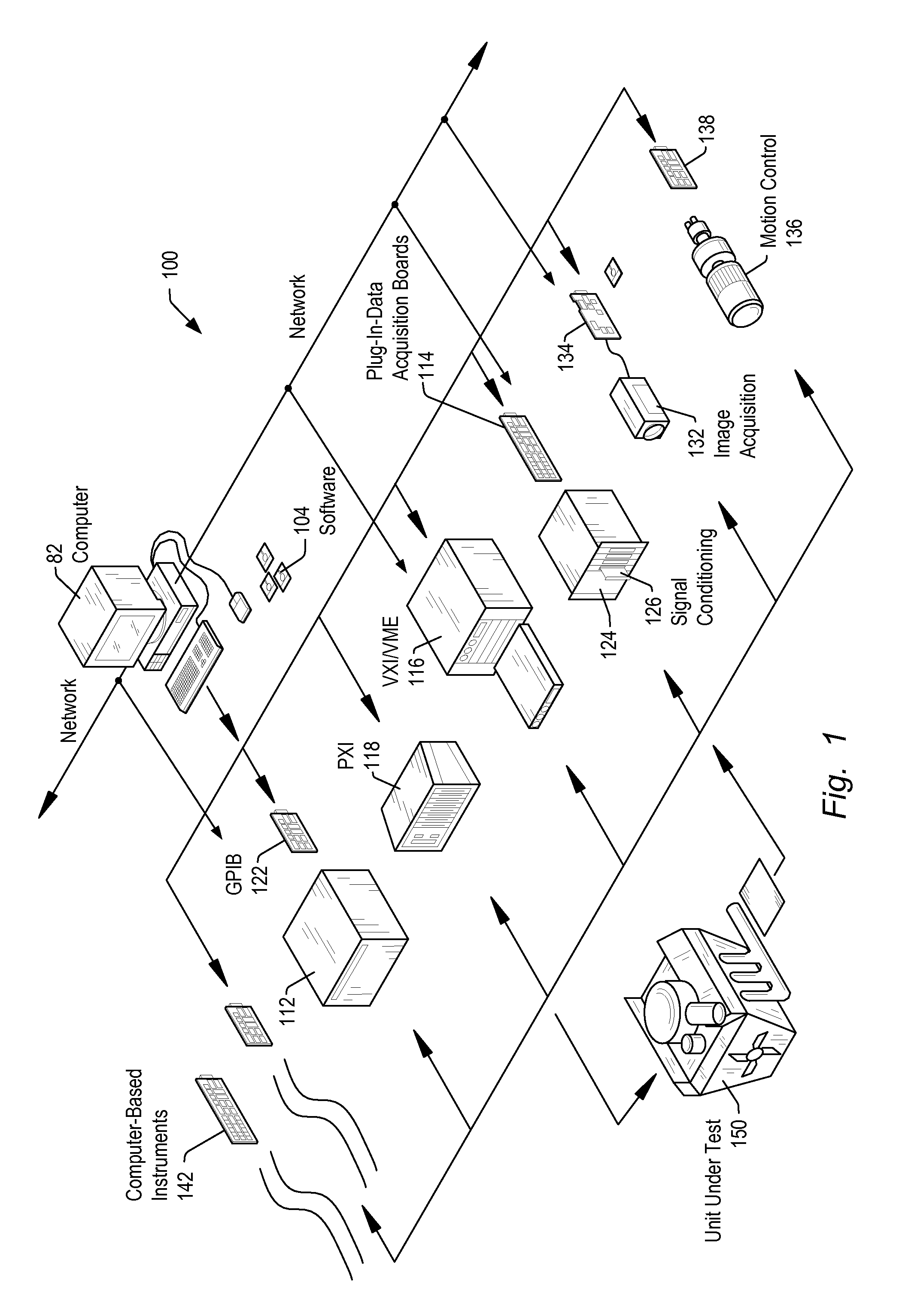
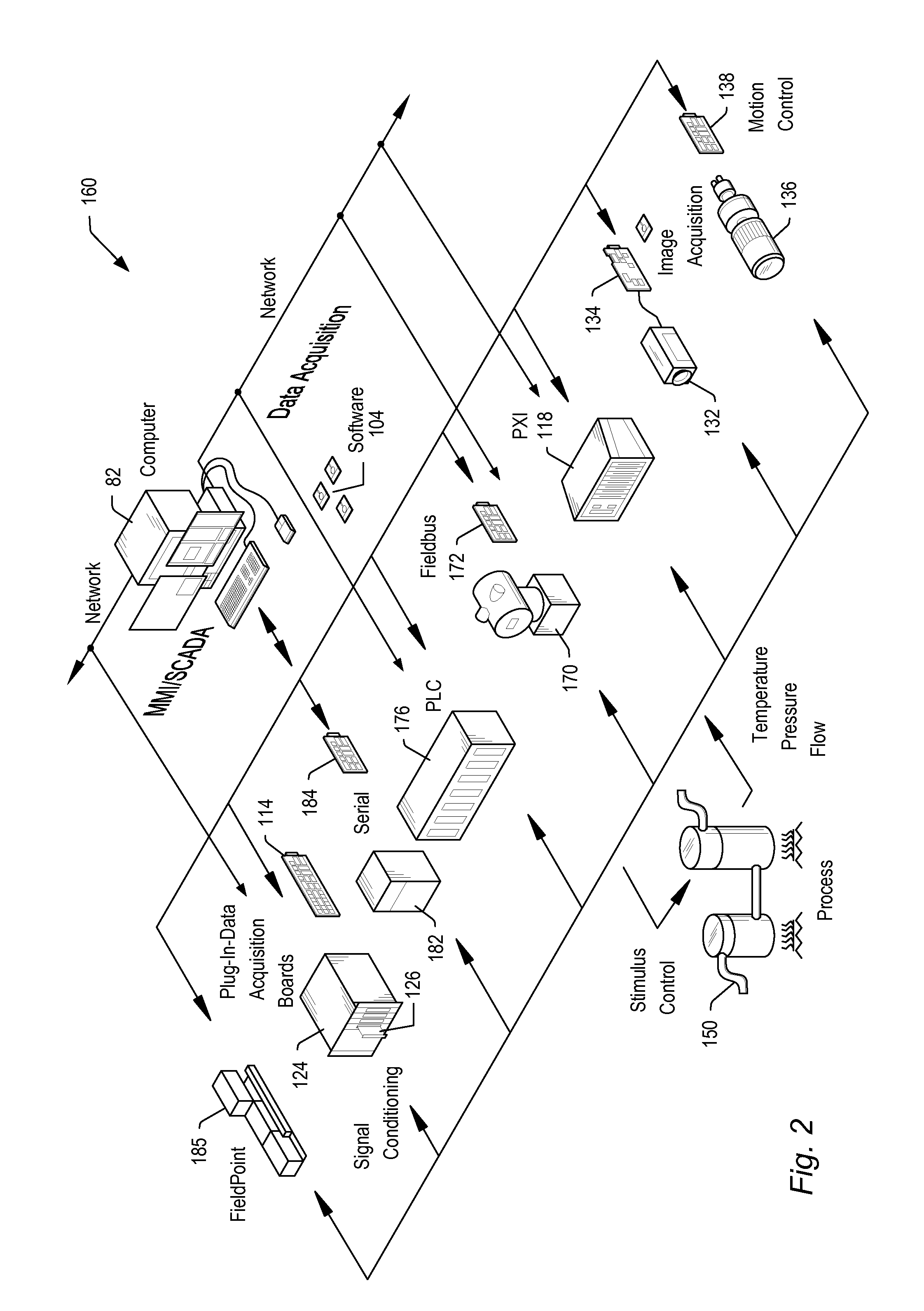
[0024]Embodiments of the present invention may be used in systems configured to perform test and / or measurement functions, to control and / or model instrumentation or industrial automation hardware, or to model and simulate functions, e.g., modeling or simulating a device or product being developed or tested, etc. More specifically, it may be used in various instances where input protection for instrumentation equipment is required, without degrading the performance of the protected instrumentation equipment. However, it is noted that the present invention may equally be used for a variety of applications, and is not limited to the applications enumerated above. In other words, applications discussed in the present description are exemplary only, and the present invention may be used in any of various types of systems. Thus, the system and method of the present invention may be used in any number of different applications.

[0025]FIG. 1 illustrates an exemplary instrumentation control ...


PUM


Abstract

Various embodiments of a self-calibration circuit may solve the problem that arises in high performance oscilloscopes and in particular, RF oscilloscopes, of internally providing a precision calibration signal without degrading the bandwidth, flatness of the frequency response, and input return loss of the oscilloscope. The self-calibration circuit may be configured to implement an impedance transformation technique where active and passive circuit elements with carefully chosen values are configured in an impedance converter. During self-calibration, switching elements comprised in the self-calibration circuit may be toggled to create a servo loop comprising an amplifier within the circuit, with an attenuator and resistive component acting as feedback elements. The circuit may hence become an impedance gyrator and behave as a precision source with an impedance matching the input impedance of the load circuit.

Description

PRIORITY CLAIM[0001]This application claims benefit of priority of provisional application Ser. No. 61 / 076,415 titled “Self-Calibration Circuit With Gyrated Output Impedance”, filed on Jun. 27, 2008, whose inventors are Mark Whittington and Zaher Harb, and which is hereby incorporated by reference as though fully and completely set forth herein.FIELD OF THE INVENTION[0002]The present invention relates to the field of instrumentation, and more particularly to the design of a self-calibration circuit with gyrated output impedance.DESCRIPTION OF THE RELATED ART[0003]In many industrial applications (and others), instruments collect data or information from an environment or unit under test (UUT), and may also analyze and process acquired data. Some instruments provide test stimuli to a UUT. Examples of instruments include oscilloscopes, digital multimeters, pressure sensors, arbitrary waveform generators, digital waveform generators, etc. The information that may be collected by respect...

Claims


Application Information

Patent Timeline
Patent Type & Authority Applications(United States)
IPC IPC(8): G01R35/04
CPCG01R35/002H03H11/30H03H7/40H03H7/24
Inventor WHITTINGTON, MARKHARB, ZAHER G.
Owner NATIONAL INSTRUMENTS
Learn More