
Electrically small antenna

Inactive Publication Date: 2009-12-31
WIRELESS FIBER SYST
View PDF3 Cites 6 Cited by
  • Summary
  • Abstract
  • Description
  • Claims
  • Application Information

AI Technical Summary

Benefits of technology

[0011]Accordingly, an object of the present invention is to provide improved electrically small antennas.

Problems solved by technology

However, in some instances, particularly in low frequency and portable applications, the dimensions of a wavelength related antenna become impractical.
For example, at 1 kHz the free space wavelength is 300 km while in seawater this is reduced to 50 m. However, these are still impracticably large dimensions for the wavelength related antennas conventionally used in through-air radio systems.
Electrically small loop antennas are therefore intrinsically poor generators or receivers of propagating radio waves.

Method used


Image

  • Electrically small antenna
  • Electrically small antenna
  • Electrically small antenna

Examples


Embodiment Construction

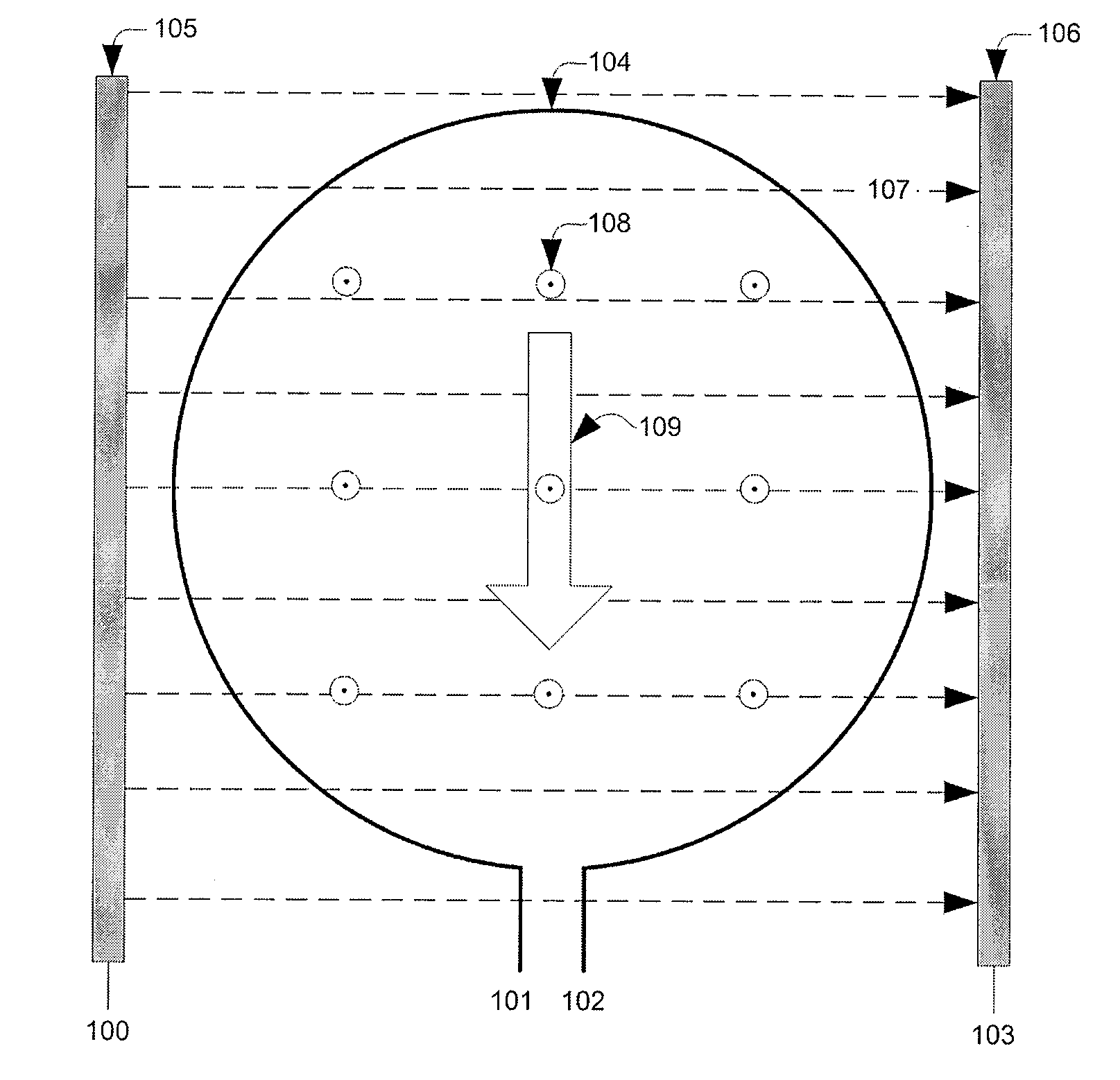
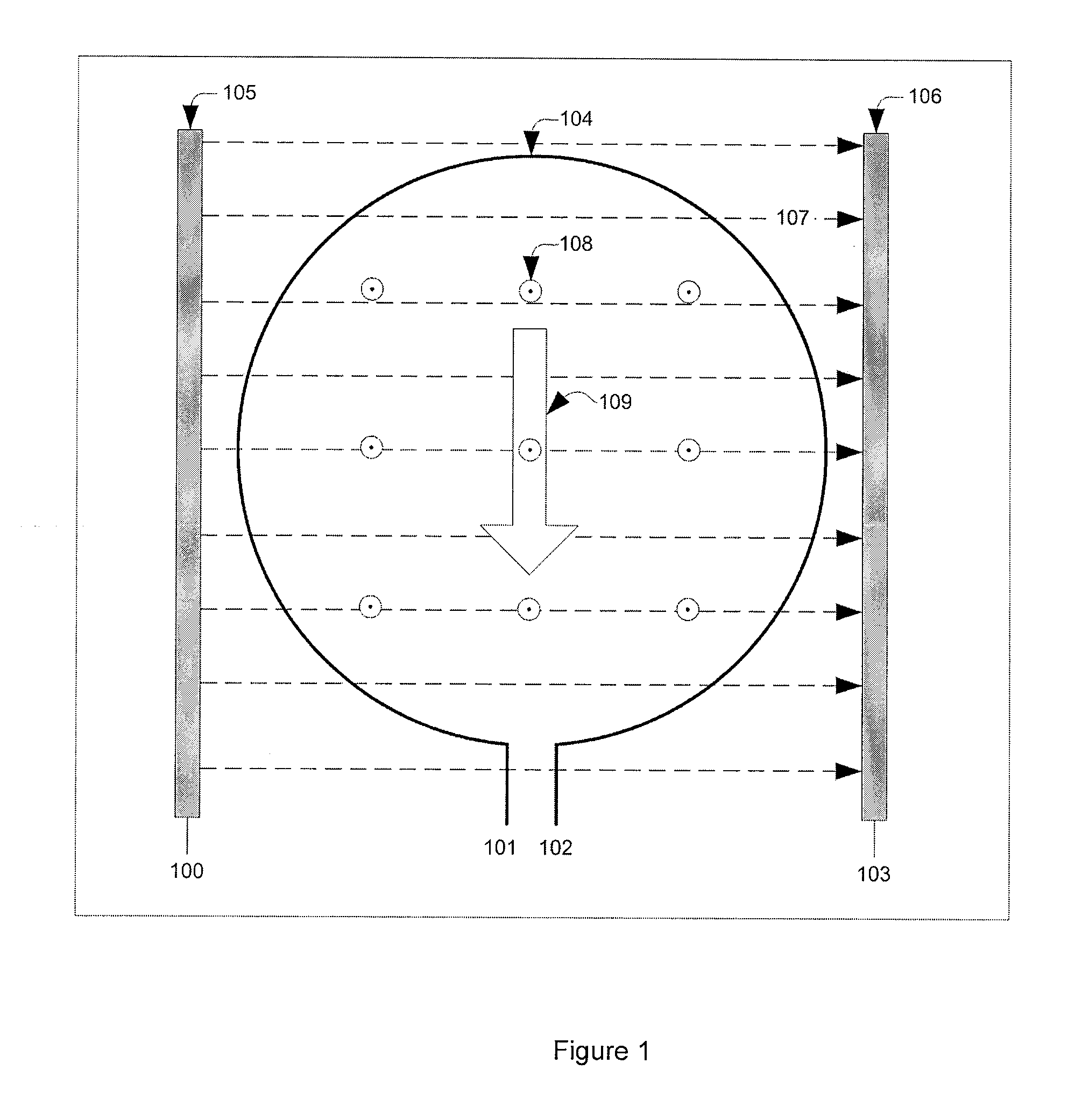
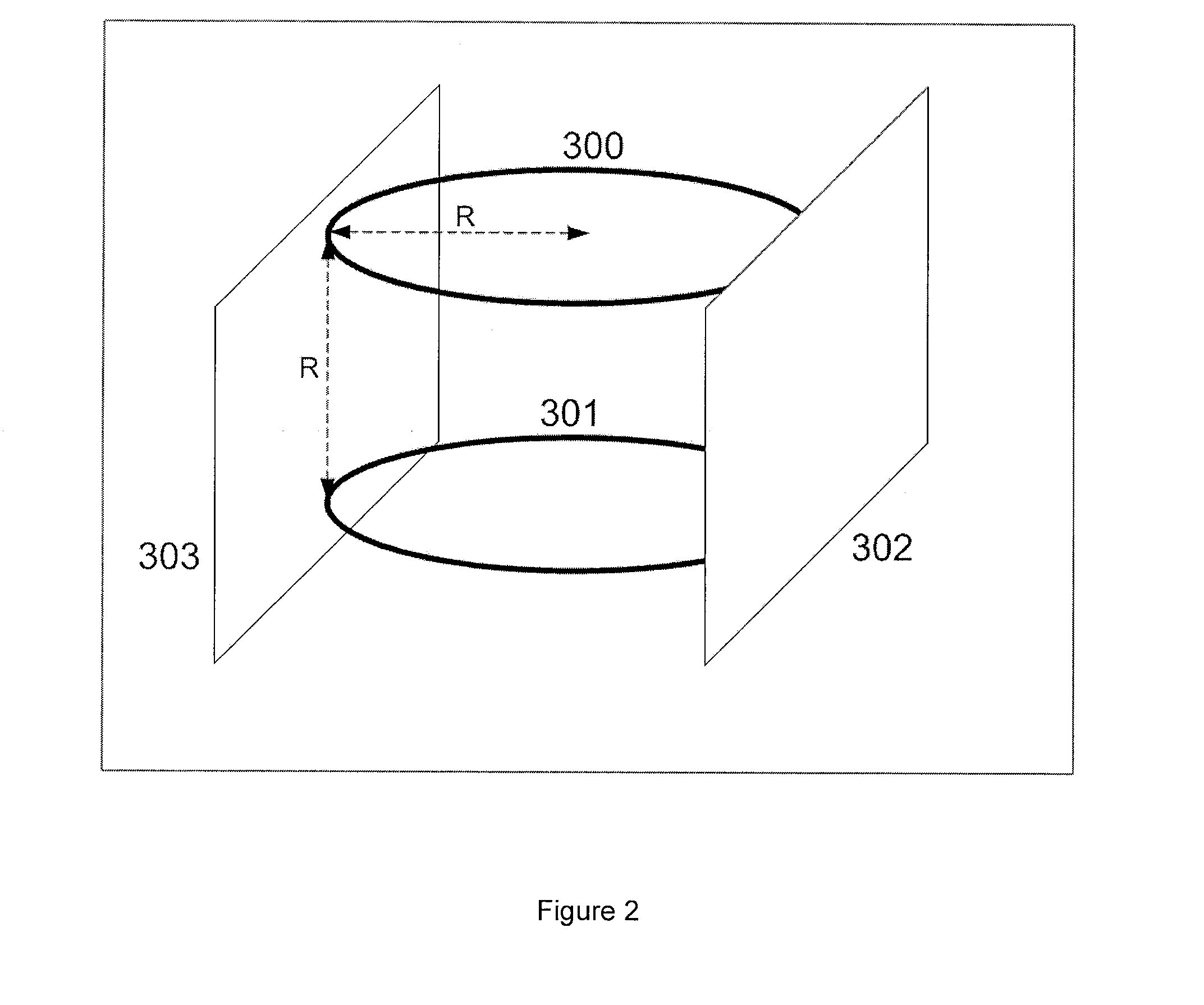
[0026]In one embodiment, the present invention is an antenna system that synthesizes a propagating wave by controlled combination of independent E and H field transducers to match the natural E-H relationship given by the medium's intrinsic impedance. While the time-phase relationship between E and H field is 0° for a propagating wave in air, the phase angle and relative magnitude changes for different propagation media. To achieve optimum efficiency, and in accordance with the invention, the relative phase and magnitude of the generated E and H fields are controlled to match the intrinsic impedance of the medium and hence preferentially launch a propagating wave at the antenna. This is particularly useful in underwater radio applications where the frequency dependence of radio attenuation leads to operation at very low radio frequencies where wavelength related antenna designs become impracticably large.

[0027]The antenna system of the present invention can act to receive propagatin...


PUM


Abstract

An antenna system, with a loop antenna and a loop current, is provided for transmitting an electromagnetic signal through a medium. The loop antenna has an E field transducer that generates an E field, and an H field transducer that generates an H field. The E and H fields are orthogonal in space and have at least one of a magnitude and phase relationship that is matched to an intrinsic impedance of a medium to generate a propagating wave. In an insulating medium the loop current lags an E field plate voltage by 90° to produce in phase E and H fields. In a conductive medium current is applied to the loop with a 135° phase lag with respect to a voltage across the E field plates. The H field is generated by the current component and leads current by 90°.

Description

CROSS-REFERENCE TO RELATED APPLICATIONS[0001]This application claims the benefit of UK application GB0724702.6 filed Dec. 19, 2007 and U.S. Ser. No. 61 / 014,793 filed Dec. 19, 2007, both of which applications are incorporated herein by reference.BACKGROUND OF THE INVENTION[0002]1. Field of the Invention[0003]This invention relates generally to electrically small antenna, and more particularly to electrically small antenna systems suitable for waves propagating through water.[0004]2. Description of the Related Art[0005]Electrically large antennas with dimensions of a fraction of a wavelength are well known for efficient launch and reception of electromagnetic signals. The half wave dipole and quarter wave antenna are typical examples. However, in some instances, particularly in low frequency and portable applications, the dimensions of a wavelength related antenna become impractical.[0006]Underwater radio applications differ from through air communications primarily due to the conduct...

Claims


Application Information

Patent Timeline
IPC IPC(8): H01Q7/00H01Q21/00
CPCH01Q1/36G01R29/0878H01Q1/04H01Q7/00H01Q9/00H01Q21/29
Inventor RHODES, MARKHYLAND, BRENDAN
Owner WIRELESS FIBER SYST
Learn More