Method and apparatus for detecting two simultaneous touches and gestures on a resistive touchscreen

a touchscreen and resistive technology, applied in the field of resistive touchscreen systems, can solve the problems of ambiguity between a single touch and the specific location of two touches, and achieve the effect of reducing the bias load resistan

Inactive Publication Date: 2009-12-31
TE CONNECTIVITY CORP
View PDF20 Cites 170 Cited by
  • Summary
  • Abstract
  • Description
  • Claims
  • Application Information

AI Technical Summary

Problems solved by technology

Unfortunately, when a user touches the resistive touchscreen with two fingers, creating two touch points or dual touch, the specific locations of two touches cannot be determined.
Instead, the system reports a single point somewhere on the line segment between the two touch points as the selected point, which is particularly misleading if the touch system cannot reliably distinguish between single-touch and multiple-touch states.
However, in this method there is an ambiguity between a single touch that simply moved rapidly to a different location and a transition to a multiple-touch state.

Method used


Image

  • Method and apparatus for detecting two simultaneous touches and gestures on a resistive touchscreen
  • Method and apparatus for detecting two simultaneous touches and gestures on a resistive touchscreen
  • Method and apparatus for detecting two simultaneous touches and gestures on a resistive touchscreen

Examples


Embodiment Construction

[0027]The foregoing summary, as well as the following detailed description of certain embodiments of the present invention, will be better understood when read in conjunction with the appended drawings. To the extent that the figures illustrate diagrams of the functional blocks of various embodiments, the functional blocks are not necessarily indicative of the division between hardware circuitry. Thus, for example, one or more of the functional blocks (e.g., processors or memories) may be implemented in a single piece of hardware (e.g., a general purpose signal processor or random access memory, hard disk, or the like). Similarly, the programs may be stand alone programs, may be incorporated as subroutines in an operating system, may be functions in an installed software package, and the like. It should be understood that the various embodiments are not limited to the arrangements and instrumentality shown in the drawings.

[0028]As used herein, an element or step recited in the singu...


PUM


Abstract

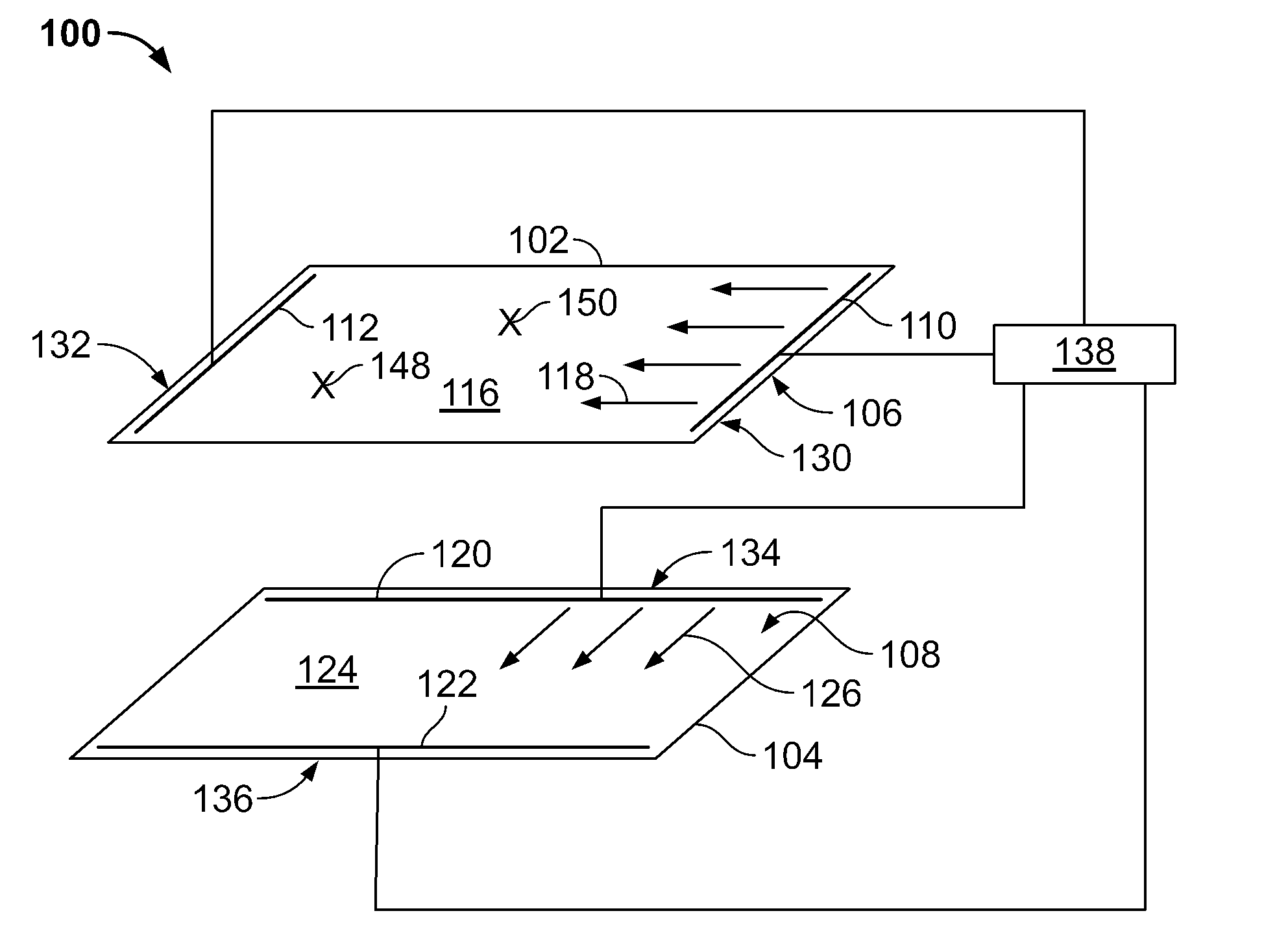
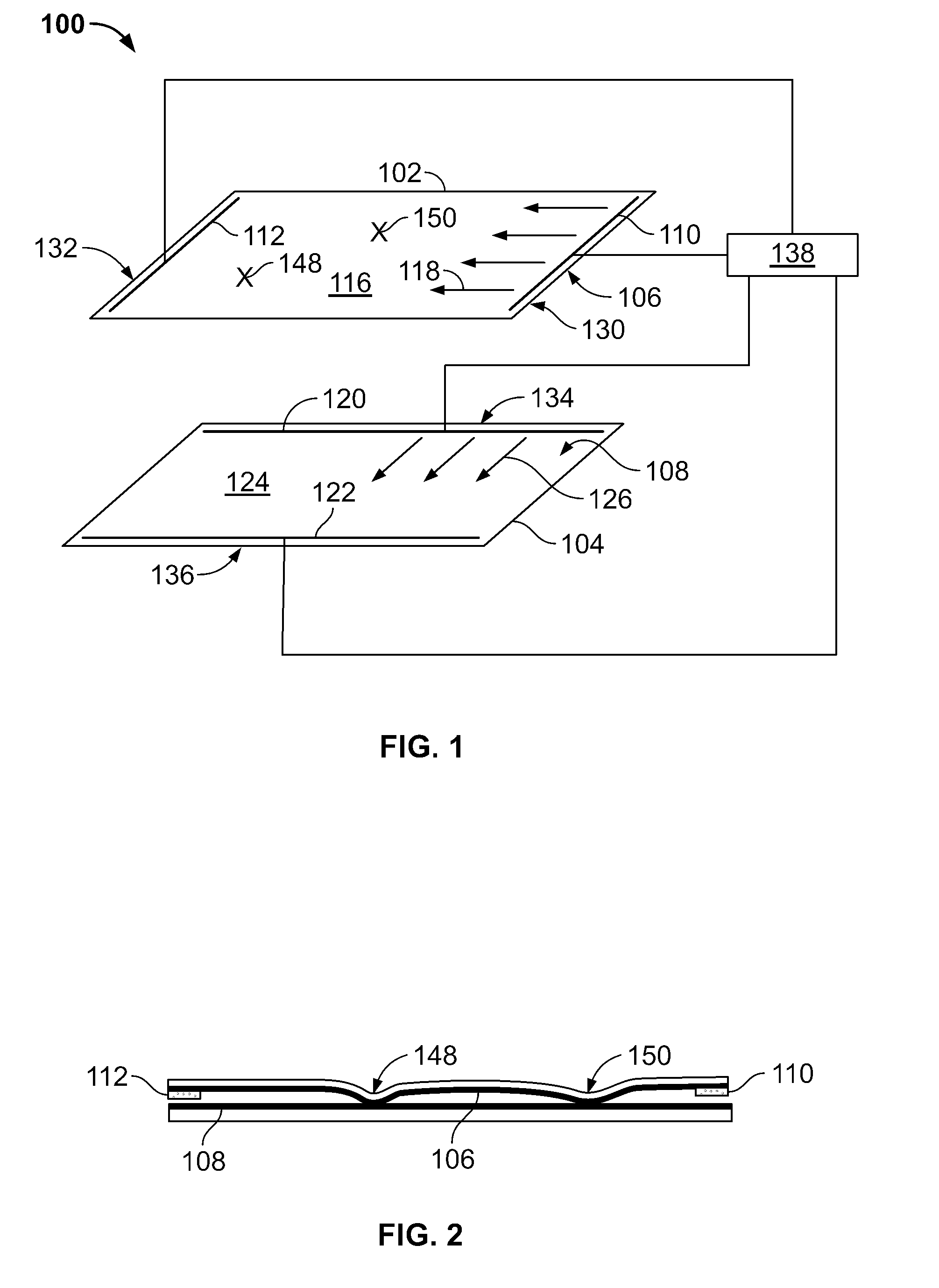
Resistive touchscreen system has substrate and coversheet with first and second conductive coatings. The substrate and coversheet are positioned proximate each other such that the first conductive coating faces the second conductive coating. The substrate and coversheet are electrically disconnected with respect to each other in the absence of a touch. First set of electrodes is formed on the substrate for establishing voltage gradients in first direction. Second set of electrodes is formed on the coversheet for establishing voltage gradients in second direction wherein the first and second directions are different. Controller biases the first and second sets of electrodes in first and second cycles and senses a bias load resistance associated with at least one of the sets of electrodes. The bias load resistance has a reference value associated with no touch. A decrease in the bias load resistance relative to the reference value indicates two simultaneous touches.

Description

BACKGROUND OF THE INVENTION[0001]This invention relates generally to touchscreen systems and more particularly to resistive touchscreen systems.[0002]Resistive touchscreens are used for many applications, including small hand-held applications such as mobile phones and personal digital assistants. Unfortunately, when a user touches the resistive touchscreen with two fingers, creating two touch points or dual touch, the specific locations of two touches cannot be determined. Instead, the system reports a single point somewhere on the line segment between the two touch points as the selected point, which is particularly misleading if the touch system cannot reliably distinguish between single-touch and multiple-touch states. In a conventional approach, the transition to a multiple-touch state may be detected by a sudden shift in measured coordinates from the first location to a new location. However, in this method there is an ambiguity between a single touch that simply moved rapidly...

Claims


Application Information

Patent Timeline
Patent Type & Authority Applications(United States)
IPC IPC(8): G06F3/045
CPCG06F3/045G06F2203/04104G06F2203/04808G06F3/04883
Inventor D'SOUZA, HENRY M.DIETZ, RAEANNE L.KENT, JOEL C.MARTCHOVSKY, DETELINWYNNE, JR., JAMES R.
Owner TE CONNECTIVITY CORP
Why Eureka
Try Eureka