Ray tracing system architectures and methods

a technology of ray tracing system and architecture, applied in image memory management, instruments, computing, etc., can solve the problem that simply providing more computation capability does not necessarily allow a suitable scaling of ray tracing speed and efficiency

Active Publication Date: 2009-12-31
IMAGINATION TECH LTD
View PDF46 Cites 90 Cited by
  • Summary
  • Abstract
  • Description
  • Claims
  • Application Information

AI Technical Summary

Benefits of technology

[0013]Example methods that can be used in ray tracing comprise providing shapes comprising scene objects in a 3-D scene to be rendered. The objects can be composed of primitives. The shapes also comprise an acceleration structure comprising elements that bound selections of the primitives. The method comprises defining a plurality of rays to be processed. The processing for the rays comprises identifying a respective closest intersection, if any, with the primitives and shading such an intersection by executing one or more code modules. The processing described above is performed for each of the rays. The processing is scheduled by making collections of the rays based on outputs produced during processing. Each ray is concurrently collectible into a plurality of the collections. Each collection is associated with at least one of the shapes. The method can effect scheduling of the processing by selecting rays for performance of further processing by selecting one or more collections to which those rays belong.

Problems solved by technology

However, simply providing more computation capability does not necessarily allow a suitable scaling of ray tracing speed and efficiency.
One reason for this is that such parallelization does not account for how data composing the scene, or an acceleration structure that increases tracing efficiency can be accessed in an efficient manner.

Method used


Image

  • Ray tracing system architectures and methods
  • Ray tracing system architectures and methods
  • Ray tracing system architectures and methods

Examples


Embodiment Construction

[0035]The following description is presented to enable a person of ordinary skill in the art to make and use various aspects of the inventions. Descriptions of specific techniques, implementations and applications are provided only as examples. Various modifications to the examples described herein may be apparent to those skilled in the art, and the general principles defined herein may be applied to other examples and applications without departing from the scope of the invention.

[0036]For clarity in description, data for a certain type of object, e.g., a primitive (e.g., coordinates for three vertices of a triangle) usually is described simply as the object itself, rather than referring to the data for the object. For example, when referring to “a ray”, it is to be understood that data representative of that ray is referenced, as well as the concept of the ray in the scene.

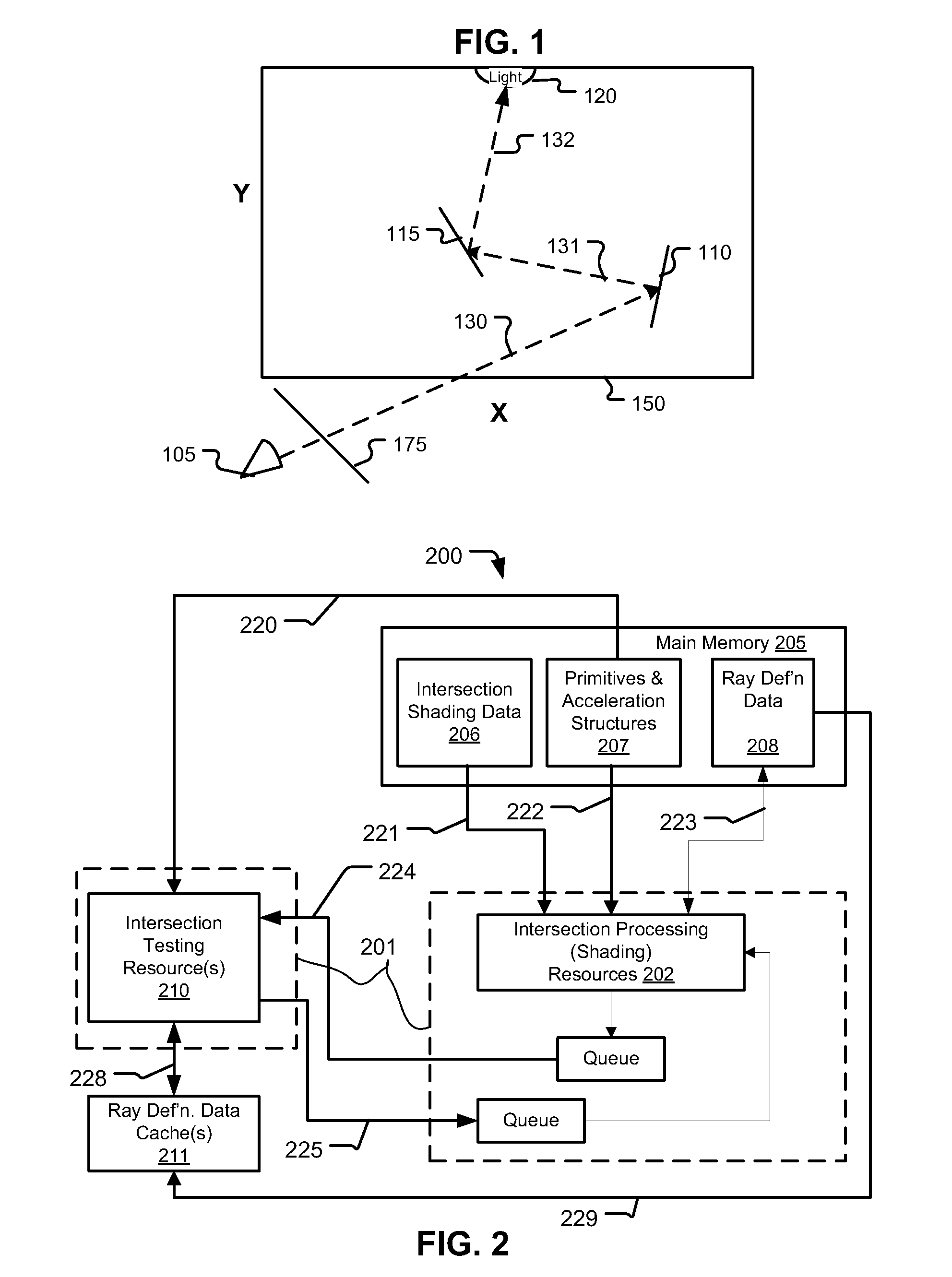
[0037]FIG. 1 illustrates a simplified scene setup, in which a 2-D plane 175 is disposed between a camera 105...


PUM


Abstract

Aspects comprise systems implementing ray tracing functionality according to example architectures. In one example, rays are collected into collections against elements of an acceleration structure, which in some cases are associated with objects composing a scene being ray traced. Indications of detected ray intersections also can be collected in an output buffer, and in some examples, the output buffer can comprise a plurality of portions, each associated with a scene object, or a common portion of code to be executed during shading. Buffer contents can be accessed in a block read. An intersection shading resource can load data to be used in shading the intersections for the identified rays, and locally storing that data for use in shading those intersections.

Description

CROSS-REFERENCE TO RELATED APPLICATIONS[0001]This application is a continuation-in-part of U.S. patent application Ser. No. 12 / 408,478, filed on Mar. 20, 2009, which is a continuation-in-part of U.S. patent application Ser. No. 11 / 856,612, which was filed on Sep. 17, 2007, and claims priority from and incorporates U.S. provisional application No. 60 / 826,201, entitled “Ray Tracing Enhancements for Graphical Rendering”, filed on Sep. 19, 2006; U.S. patent application Ser. No. 12 / 408,478 also claims priority from U.S. provisional application No. 61 / 038,731, entitled “Coupling Ray Storage and Compute for Memory-Efficient Ray Intersection Test Scaling”, filed on Mar. 21, 2008, and from U.S. provisional application No. 61 / 095,890, entitled “Architectures for Parallelized Intersection Testing and Shading for Ray-Tracing Rendering”, filed on Sep. 10, 2008; this application also claims priority from provisional app. No. 61 / 229,258, filed on Jul. 28, 2009 and from provisional app. No. 61 / 229,...

Claims


Application Information

Patent Timeline
Patent Type & Authority Applications(United States)
IPC IPC(8): G06T15/50
CPCG06T15/06G06T15/80G09G2370/10G09G5/393G09G2360/121G09G5/006G06T1/60G06T15/08G06T2215/12
Inventor PETERSON, LUKE TILMANMCCOMBE, JAMES ALEXANDERSALSBURY, RYAN R.CLOHSET, STEVEN JOHN
Owner IMAGINATION TECH LTD
Why Eureka
Try Eureka