Lamp base improvement of a street lamp

a technology of led street lamps and lamp bases, which is applied in the direction of fixed installation, lighting and heating equipment, lighting support devices, etc., can solve the problems of saving lots of costs of replacing lamp poles of street lamps

Inactive Publication Date: 2009-12-31
PYROSWIFT HOLDING CO LIMITED
View PDF3 Cites 36 Cited by
  • Summary
  • Abstract
  • Description
  • Claims
  • Application Information

AI Technical Summary

Benefits of technology

[0008]Accordingly, one object of the present invention is to provide a lamp base improvement of a street lamp, which can solve the problem of unlit areas between street lamps by setting

Problems solved by technology

Also, it can save lots of costs of r

Method used


Image

  • Lamp base improvement of a street lamp
  • Lamp base improvement of a street lamp
  • Lamp base improvement of a street lamp

Examples


Embodiment Construction

[0020]Reference will now be made to the drawing figures to describe the present invention in detail.

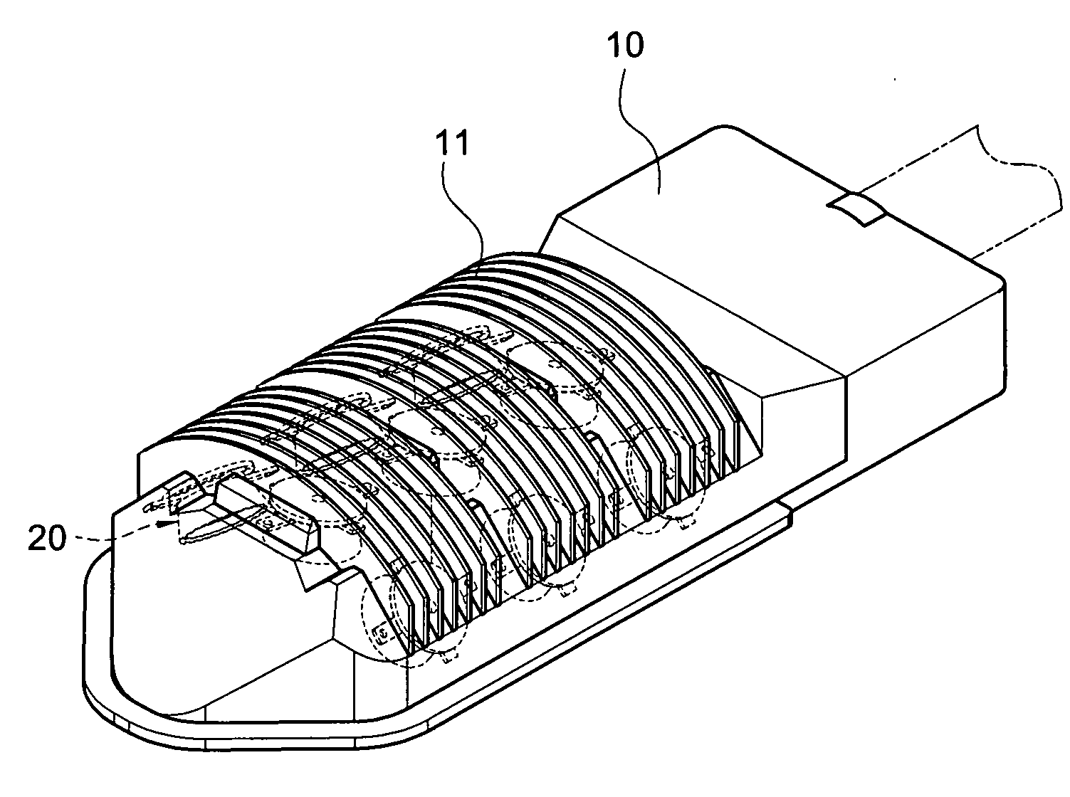
[0021]Please refer from FIGS. 2-5. The present invention is to provide a lamp base improvement of a street lamp. It includes a lamp base 10, a plurality of lighting modules 20 and a transparent mask 30. The lamp base 10 is made of die casting aluminum. A plurality of heat dissipating fins 11 and brackets 12 are disposed on the outside and inside of the lamp base 10, respectively. The brackets 12 are array arranged and bowl shaped, or a cross section of the bracket 12 is trapezoid shaped. The brackets 12 are arranged into a ladder-shape in a longitudinal direction and having at least three longitudinal lines (refer to FIG. 3 and FIG. 5). Two outside lines of brackets 12 are slanted inward for light gathering. One preferred embodiment, there is nine brackets 12 in the lamp base 10, and each bracket 12 disposing a lighting module 20. In real practice, the number of brackets 12 and its co...


PUM


Abstract

An illumination device of a lamp base improvement of a street lamp to change the projection direction is disclosed. A lamp base formed a plurality of brackets inside. Bottoms of the brackets are longitudinally set to be slanted. Lighting modules corresponding to the brackets are disposed along the bottoms. A transparent mask is combined to the lamp base to cover those lighting modules. Whereby, it can provide an LED street lamp which can change the projection direction.

Description

BACKGROUND OF THE INVENTION[0001]1. Field of the Invention[0002]The present invention relates to a light emitting diode (LED) lamp, and more particularly to a lamp base structure of an LED street lamp.[0003]2. Description of the Prior Art[0004]For a conventional mercury street lamp of illumination, the high heat resulting from long use always makes its service life limited. Because of its high power consuming and environmental pollution, it tends to be replaced by a light emitting diode (LED) illumination device for advantages of high intensity, power saving and long service life, etc.[0005]Street lamps are used to guide passengers and indicate vehicles. There has been a determined distance between two street lamps to avoid setting too many street lamps for saving costs. However, there often are unlit areas between street lamps on roads. In a worst-case, the safety of passengers is at risk.[0006]A major reason why the unlit areas exist is the included angle between a lamp base and a...

Claims


Application Information

Patent Timeline
IPC IPC(8): F21V21/00F21V29/02
CPCF21S2/005F21S8/086F21V15/01F21V19/001F21V29/763F21Y2101/02Y02B20/72F21V29/507F21V19/003F21Y2115/10
Inventor WANG, PEI-CHOA
Owner PYROSWIFT HOLDING CO LIMITED
Why Eureka
Try Eureka