Housing and mounting assembly for skylight energy management system

a skylight energy management and housing technology, applied in skylights/domes, sustainable buildings, light and heating equipment, etc., can solve the problems of diffuse light, large installation cost, and significant installation cost, so as to save installation cost and installation cost, efficient use of light, and increase the effect of light availabl

Inactive Publication Date: 2014-06-19
MBC VENTURES INC
View PDF2 Cites 5 Cited by
  • Summary
  • Abstract
  • Description
  • Claims
  • Application Information

AI Technical Summary

Benefits of technology

[0015]In order for the reflected solar resource discussed above to be harvested and brought into the building, the skylight should preferably A) have vertical surfaces that have a view of the roof surface, and B) have optics that can redirect both the upward- and downward-shining light through the aperture into the space below. Use of this scattered light as a resource for daylighting has several important advantages. First, a significant expense in the installation of any skylight is the cutting and sealing of the opening which creates the aperture for the light transmission. Making use of the scattered light from the roofing material that is adjacent to the skylight effectively increases the light available to be transmitted through the skylight without increasing the opening. That is, the same amount of light may be transmitted through a smaller roof opening, thus saving significant cost in the installation. Secondly, the light that is reflected from a bright white colored roof is diffuse, scattered light. One of the principal functions of a skylight is to take the sun's direct rays and scatter those rays, which makes more efficient use of the light and is more pleasing to the occupants in the space below. Indeed, a significant amount of the expense of construction of state-of-the-art skylights goes into optical features which are intended to do this scattering and diffusing of the sun's rays. The light reflected from the roof that is already pre-scattered does not need to be re-scattered by the skylight. Therefore, the expensive diffusing optical features of the skylight that are necessary to diffuse direct bright sunlight are not necessary when transmitting the light which has already been scattered by the bright reflective roofing. The assembly described herein provides a skylight assembly, such as one suitable for integrating an energy management system, that includes a transparent wall and very low profile curb that maximize the use of direct solar along with both diffuse and ambient light, and particularly of light reflected off of the roof surface.

Problems solved by technology

First, a significant expense in the installation of any skylight is the cutting and sealing of the opening which creates the aperture for the light transmission.
That is, the same amount of light may be transmitted through a smaller roof opening, thus saving significant cost in the installation.
Secondly, the light that is reflected from a bright white colored roof is diffuse, scattered light.
Indeed, a significant amount of the expense of construction of state-of-the-art skylights goes into optical features which are intended to do this scattering and diffusing of the sun's rays.

Method used


Image

  • Housing and mounting assembly for skylight energy management system
  • Housing and mounting assembly for skylight energy management system
  • Housing and mounting assembly for skylight energy management system

Examples


Embodiment Construction

[0028]The following description is of a particular embodiment of the invention, set out to enable one to practice an implementation of the invention, and is not intended to limit the preferred embodiment, but to serve as a particular example thereof. Those skilled in the art should appreciate that they may readily use the conception and specific embodiments disclosed as a basis for modifying or designing other methods and systems for carrying out the same purposes of the present invention. Those skilled in the art should also realize that such equivalent assemblies do not depart from the spirit and scope of the invention in its broadest form.

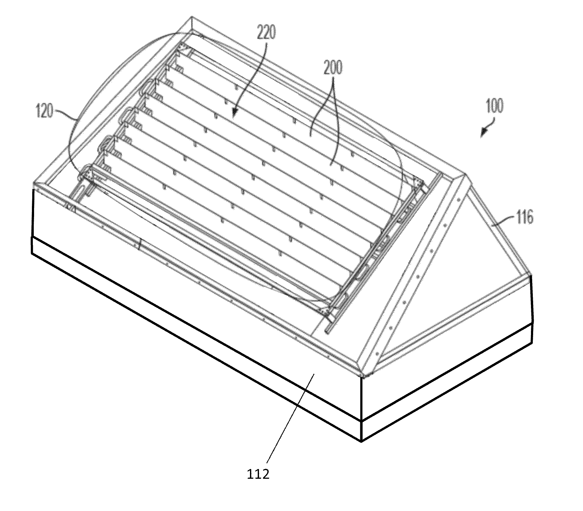
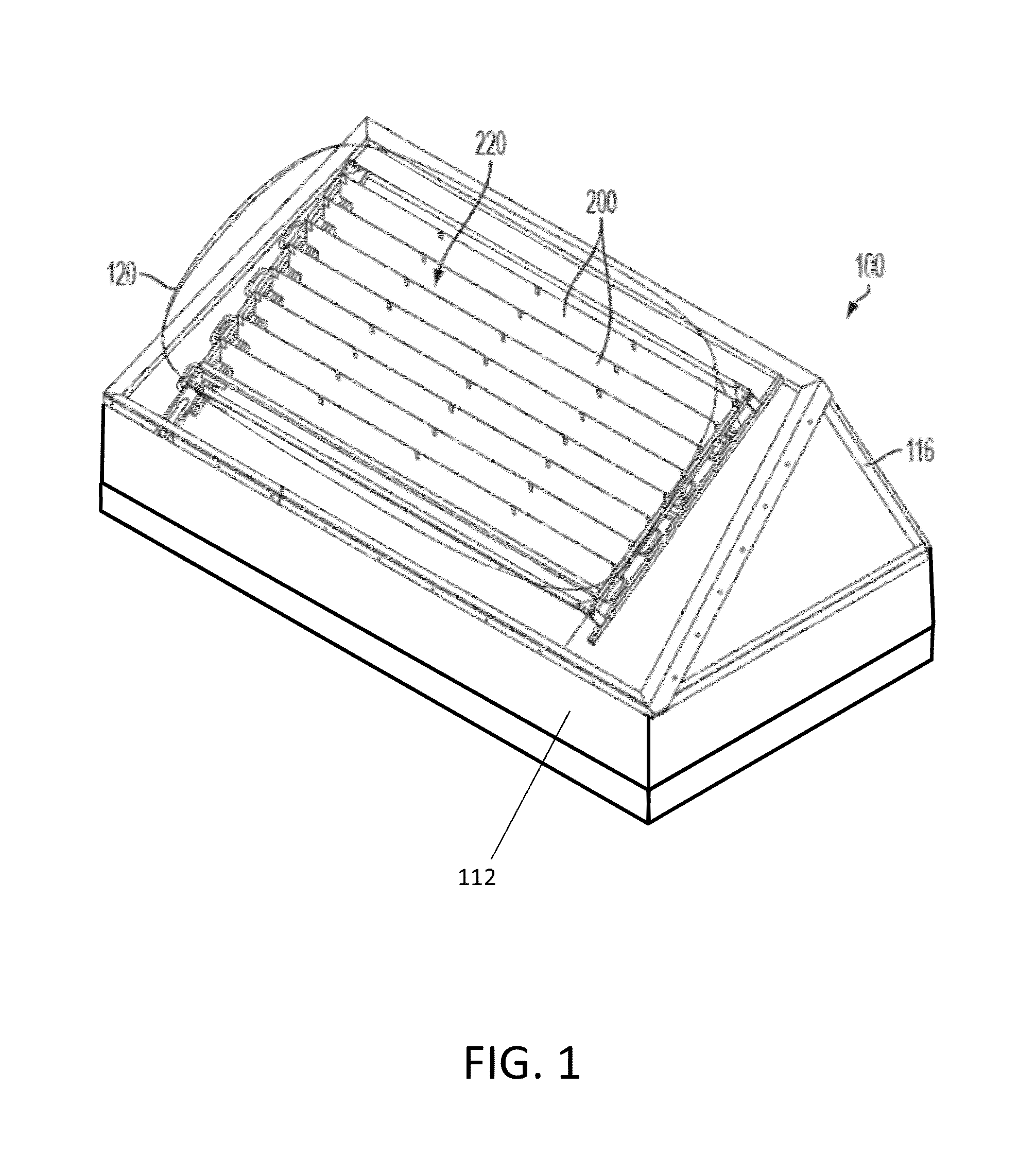
[0029]FIG. 1 shows a perspective view of an exemplary skylight module (shown generally at 100) which may incorporate the housing and mounting assembly set forth herein. The skylight module 100 is configured for installation in, for instance, the roof of a building, such as a commercial building. In accordance with an exemplary embodiment of the ...


PUM


Abstract

Disclosed is a housing and mounting assembly for a skylight module, and particularly for a skylight module that incorporates an energy management system. The housing and mounting assembly is configured to efficiently capture both direct solar and diffuse ambient light, and deliver light that is diffuse to the space below the skylight that provides even illumination and no unpleasant glare spots. The walls of the skylight module may be formed of multi-wall polycarbonate panels configured to redirect both the upward- and downward-shining light through the aperture into the space below. Moreover, the curb of the assembly may include a flexible flashing strip provided with a reflective coating configured to reflect sunlight upward through the walls of the assembly and into the skylight module, such that the advantages of collecting and using such reflected light can be achieved even in a retrofit installation on a non-reflective roofing surface.

Description

CROSS REFERENCE TO RELATED APPLICATION[0001]This application is based upon and claims benefit of copending U.S. Provisional Patent Application Ser. No. 61 / 703,330 entitled “SKYLIGHT ENERGY MANAGEMENT SYSTEM,” filed with the U.S. Patent and Trademark Office on Sep. 20, 2012 by the inventor herein, the specification of which is incorporated herein by reference in its entirety.FIELD OF THE INVENTION[0002]This invention relates to radiant energy management, and more particularly to a housing and mounting assembly for use with systems for capturing solar energy to manage illumination and temperature within a defined space.BACKGROUND OF THE INVENTION[0003]Solar generation and cogeneration systems can offer a logical alternative or addition to fossil fueled energy systems as fuel costs and environmental concerns increase. The solar heat that is collected in a collection system, with or without electricity (such as by way of photovoltaic cells), may provide a major boost to an energy system...

Claims


Application Information

Patent Timeline
Patent Type & Authority Applications(United States)
IPC IPC(8): E04D13/03F24S23/79
CPCY02B10/20E04D13/033E04D13/035E04B7/18E04D13/0351
Inventor TANDLER, JOHN JOSEPH
Owner MBC VENTURES INC
Why Eureka
Try Eureka