Energy arbitrage by load shifting

a load shifting and energy arbitrage technology, applied in the field of energy management, can solve the problems of increasing the energy cost of a utility company for generating or purchasing electrical energy, and the energy cost of the consumer is higher

Active Publication Date: 2009-12-31
GRIDPOINT
View PDF5 Cites 52 Cited by
  • Summary
  • Abstract
  • Description
  • Claims
  • Application Information

AI Technical Summary

Problems solved by technology
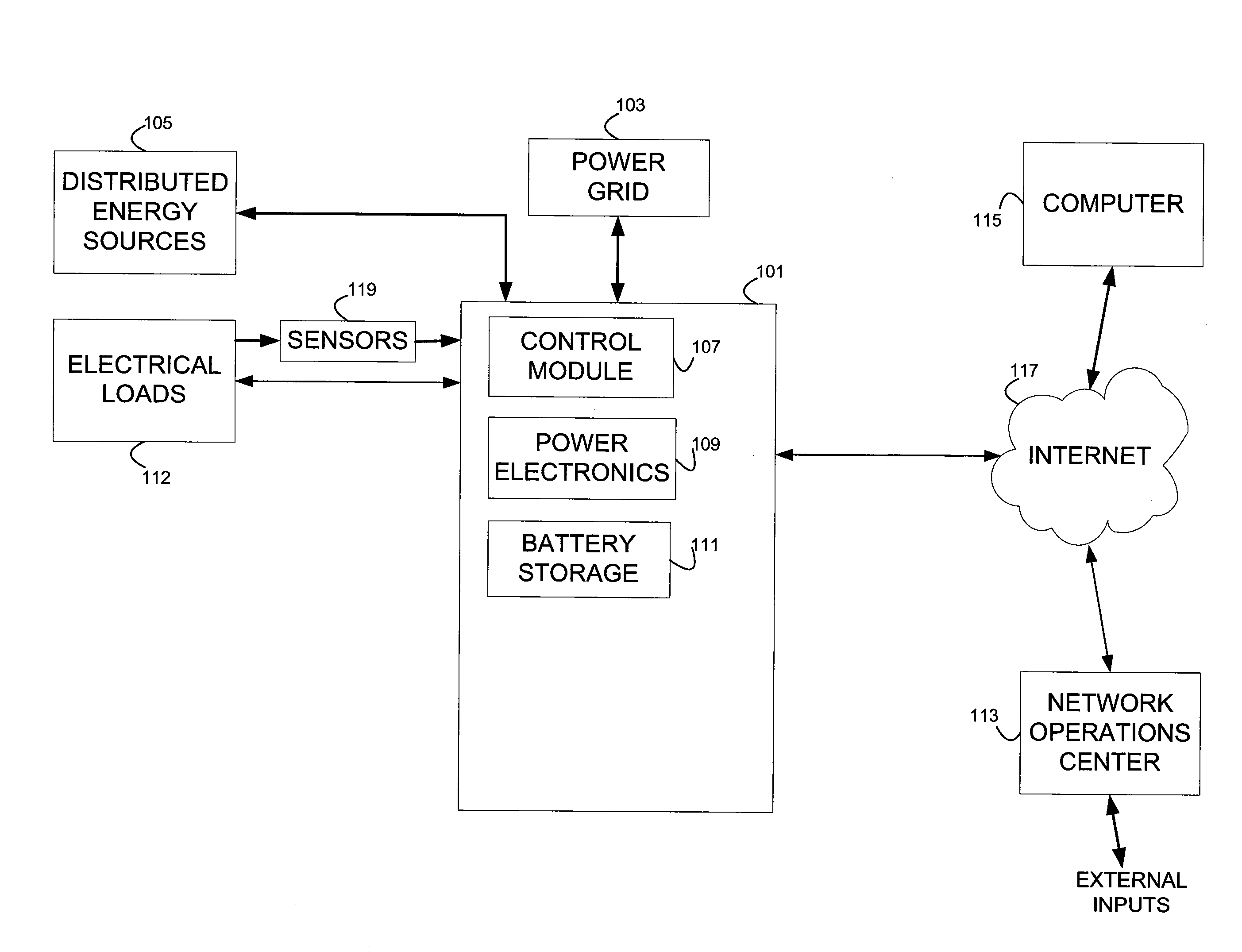
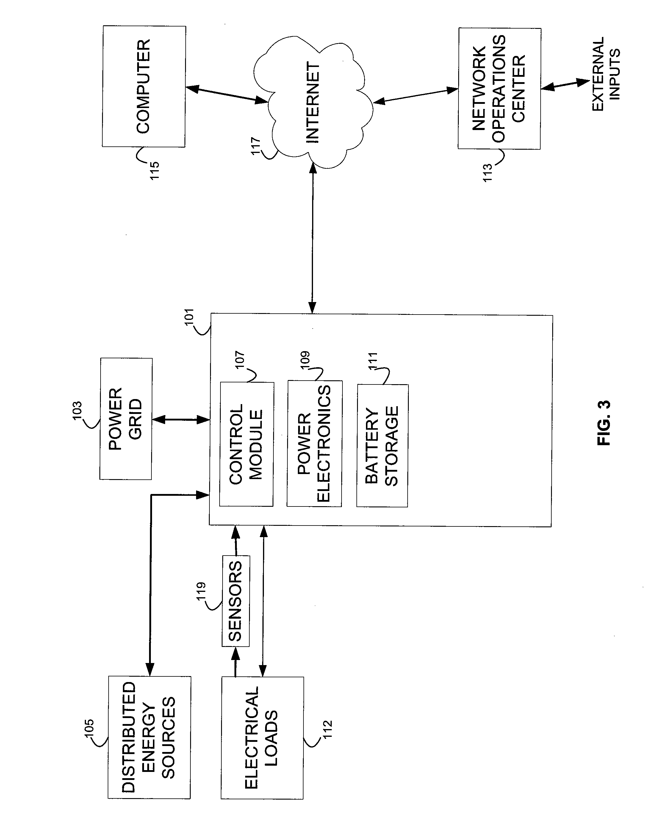
The incremental cost to a utility company for generating or purchasing electrical energy increases dramatically during periods of peak use over periods of off-peak usage.
The higher rates charged during peak usage periods can lead to significantly higher energy costs for the consumer, especially when the consumer's period(s) of high demand coincides with or falls within the interval set by the utility as peak hours.
However, such arrangements are made for the benefit of the utility, whose interests may be at odds with the interests and energy requirements of the consumer.

Method used


Image

  • Energy arbitrage by load shifting
  • Energy arbitrage by load shifting
  • Energy arbitrage by load shifting

Examples


case 1

[0079] F>R / T, then F*(Sc−C)=FSc−FI / R+I / T=F(Sc−I / R)+I / T, which is a line with a negative slope (for Scc. One can accelerate how quickly that happens, but that will mean decreasing the battery's expected life-span; and the energy bill savings due to the acceleration will not be paying for the life lost (unless Sc>I / R).

case 2

[0080] Fc−C)=F SccR / T (as long as Sc is positive) since Fc).

case 3

[0081] F=R / T=>F*(Sc−C)=ScR / T. Since the longest battery life that can be expected to be achieved is the rated life T, and the greatest savings that can be achieved is R*Sc, both may be expected to be achieved when the cycle rate is R / T. The energy bill savings Sc does not depend on cycling frequency. Thus, the benefit is maximized with R cycles and energy bill savings S, (saving R*Sc dollars) providing a battery lifetime of T years. Unless the total energy bill savings were greater than the initial cost of the battery (R*Sc>I), it would be counter-productive to hasten the battery's demise by a single day.

[0082]Cycles Needed for Backup

[0083]Suppose Q cycles are needed by the battery to last T years providing backup. In this case, it would be assumed that the rated cycles R>=Q. Thus R-Q cycles (the unreserved cycles) can be used for other purposes because those cycles were bought for battery backup but are unnecessary to accomplish that task.

[0084]Cycle Budgets

[0085]It has been shown ...


PUM


Abstract

Methods and systems are provided for realizing energy cost savings through load shifting utilizing a battery bank that may serve as a battery back-up on a premises for providing power in the event of a grid power outage or curtailment. A budget of unreserved cycles of battery charging and discharging is determined, taking into account the rated battery life in terms of both time (e.g., years) and number of cycles. That cycle budget is allocated to days of the year identified as days on which the greatest savings can be realized through load shifting. These days are identified by taking into account the peak and off-peak usage rates applicable on those days, any rate tiers that may be entered as a result of the additional energy expended to load shift, and the round trip efficiency of the charge / discharge cycles. Load shifting is executed in accordance with an established schedule of the identified days, by discharging the batteries during peak usage hours and charging the batteries during off-peak periods. In the event the budget of unreserved cycles exceeds the number of profitable days for load shifting, the depth of discharge on each cycle may be increased to realize greater savings on the scheduled days, at the tolerable cost of losing cycles not expected to be used in any event.

Description

[0001]This patent application is a continuation of U.S. patent application Ser. No. 11 / 558,068 filed Nov. 9, 2006. The disclosure of the above application is incorporated herein by reference.BACKGROUND[0002]The present invention relates generally to energy management, and more particularly to electrical energy load shifting in order to reduce energy costs. More particularly, the invention concerns systems and methods that permit electrical energy to be purchased and stored during off-peak hours, and the stored energy to be used and / or sold back to the power grid during peak hours, to thereby realize savings in energy costs.[0003]Energy demand at a premises typically varies over the time of day. In a typical home, there is a peak in the morning when the family gets up, turns on lights, radios and televisions, cooks breakfast, and heats hot water to make up for the amount used in showers. When the family leaves for work and school, it may leave the clothes washer and dishwasher runnin...

Claims


Application Information

Patent Timeline
Patent Type & Authority Applications(United States)
IPC IPC(8): H02J15/00G06F17/00
CPCH02J3/32G06Q50/06Y04S20/222Y02B70/3225
Inventor HAKIM, DAVID B.DANLEY, DOUGLAS RICARDOCAPLAN, MICHAEL
Owner GRIDPOINT
Why Eureka
Try Eureka