Transporter vehicle

a technology for transporting vehicles and vehicles, applied in the field of transporting vehicles, can solve the problems of engine damage, engine unfavorable disposal, engine cost, etc., and achieve the effect of improving the operating efficiency

Active Publication Date: 2010-01-07
HITACHI CONSTR MASCH CO LTD
View PDF3 Cites 12 Cited by
  • Summary
  • Abstract
  • Description
  • Claims
  • Application Information

AI Technical Summary

Benefits of technology

[0015]In view of the above-described problems of the prior art, an object of the present invention is to provide a transporter vehicle with which the operation of m

Problems solved by technology

Therefore, for example, at the time of mounting or dismounting the engine to or from the base frame, the upper cross beam constitutes a hindrance, and the following problem occurs.
Namely, since the engine serving as a prime mover of the transporter vehicle is mounted on the base frame by being positioned on the front side of the loading platform, the engine is unfavorably disposed such that the left and right sides are sandwiched between the left and right column portions of the base frame, and the upper side is covered by the upper cross beam.
It should be noted that the engine is an expensive product (part), and if the upper cross beam is welded after mounting the engine on the base frame, there is a possibility of the engine becoming damaged by sparks and the like during welding.
Thus, a time-consuming operation is required.
Moreover, in case the engine is collided against a peripheral member (e.g., e

Method used


Image

  • Transporter vehicle
  • Transporter vehicle
  • Transporter vehicle

Examples


Embodiment Construction

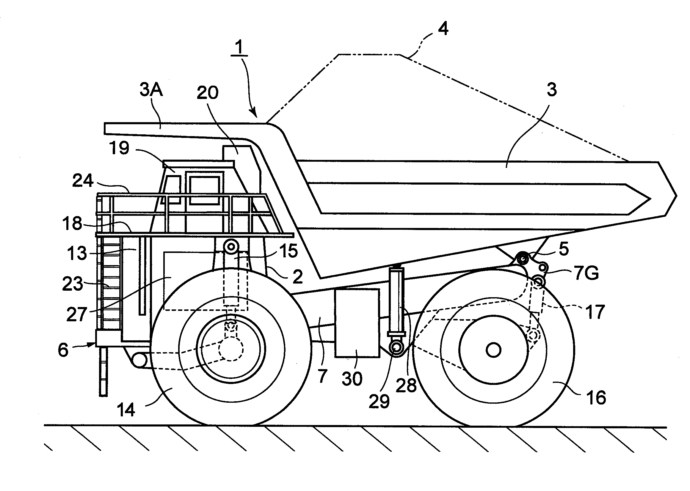
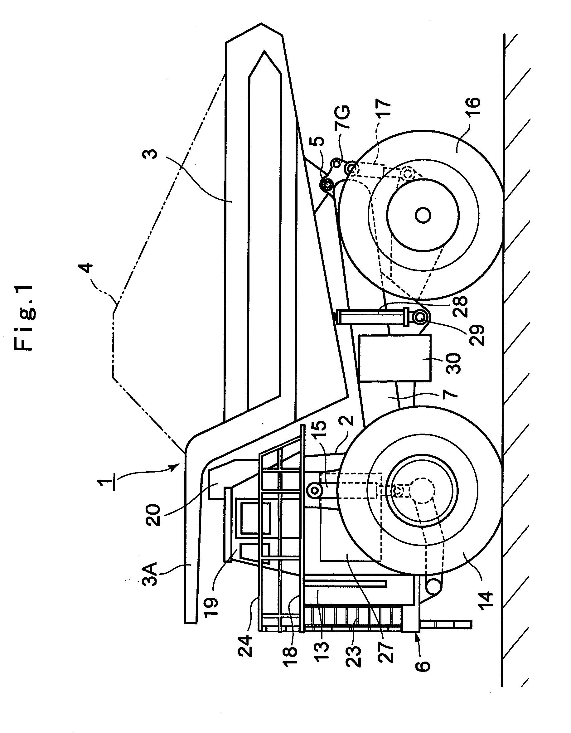
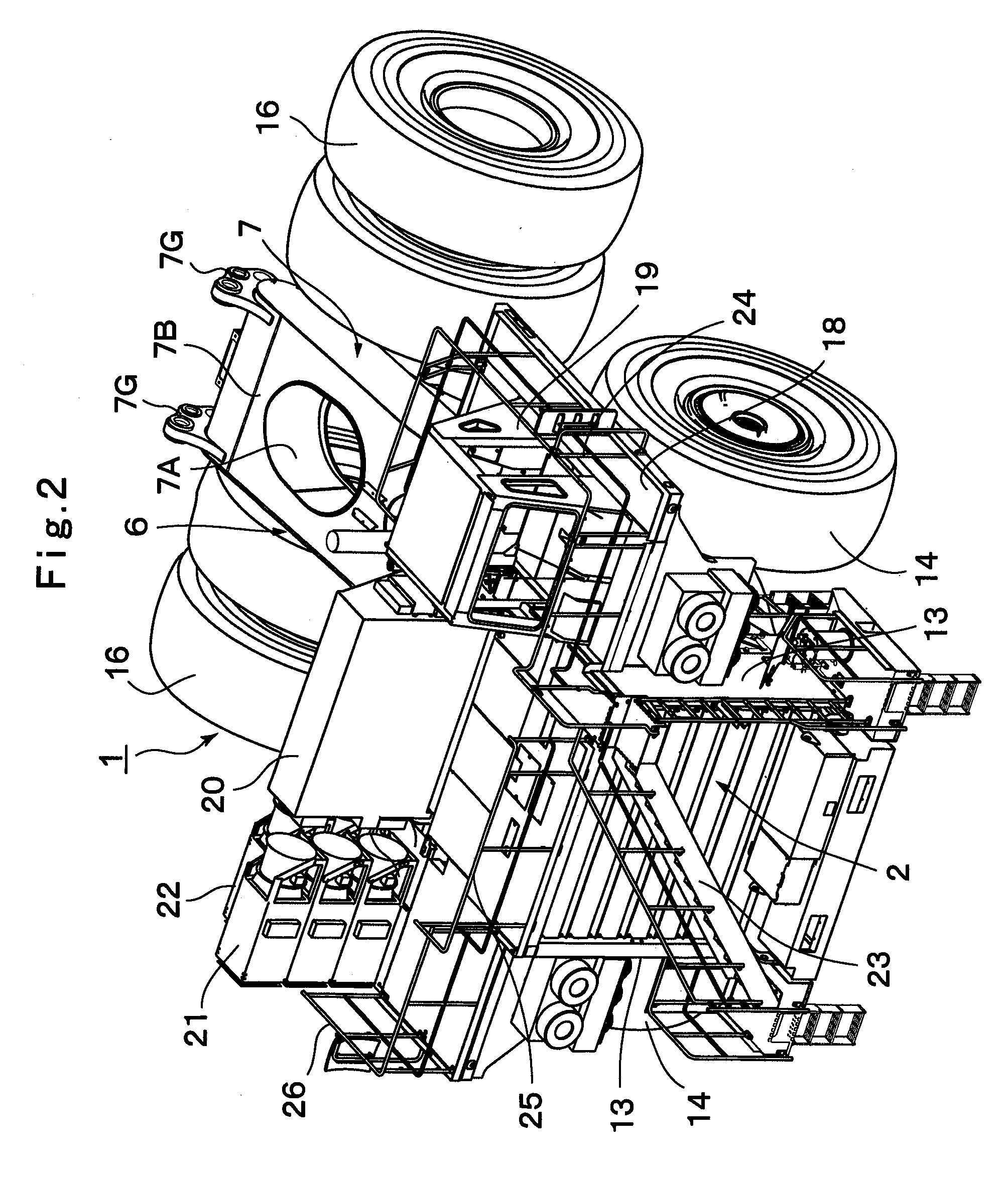
[0038]Hereafter, referring to the accompanying drawings, a detailed description will be given of a transporter vehicle in accordance with an embodiment of the invention by citing as an example a dump truck which transports crushed stones excavated from a mine.

[0039]Here, FIGS. 1 to 9 show an embodiment of the invention. In the drawings, denoted at 1 is a dump truck which is a large-size transporter vehicle. As shown in FIGS. 1 and 2, the dump truck 1 is largely comprised of a vehicle body 2 forming a rigid frame structure and a vessel 3 serving as a loading platform which is tiltably mounted on the vehicle body 2. Further, the vehicle body 2 is formed by including, among others, a frame 6, a housing 13, a floor 18, and a cab 19, which will be described later.

[0040]In addition, the vessel 3 is formed as a large-size container whose overall length reaches as much as 10 to 14 meters to load a large volume of heavy objects to be transported such as crushed stones or other similar object...


PUM


Abstract

An upper cross beam 10 for supporting a rear side of a cab 19 from below is formed as a separate member from a base frame 7. This upper cross beam 10 is separably mounted on left and right column portions 7E of the base frame 7 by using bolts 12. Namely, when an engine 27 is mounted to the base frame 7, the upper cross beam 10 is separated in advance from the base frame 7. Consequently, at the time of the operation of carrying in the engine 27, it merely suffices to vertically hoist or lower the engine 27 by use of a crane. It is thereby possible to carry in the engine 27 between the column portions 7E of the base frame 7 without being hampered by the upper cross beam 10.

Description

BACKGROUND ART[0001]1. Field of the Invention[0002]The present invention relates to a transporter vehicle which is suitably used in transporting such as crushed stones or earth and sand excavated from such as an open-pit stope, a mine, or the like.[0003]2. Description of Prior Art[0004]In general, a large-size transporter vehicle called a dump truck has a tiltable vessel (loading platform) on a frame of a vehicle body, and transports objects to be transported such as crushed stones or earth and sand or the like to an unloading site of, for instance, an exit port or the like in a state in which the objects to be transported are loaded in a large quantity on the vessel.[0005]A transporter vehicle of this type according to the prior art is comprised of a frame extending in the forward and rearward direction; a loading platform which is tiltably provided on a rear portion of the frame so as to load the objects to be transported; an engine which is mounted on the frame by being positione...

Claims


Application Information

Patent Timeline
IPC IPC(8): B60P1/04
CPCB62D21/186
Inventor FUSHIKI, MICHIOKOZAWA, HAJIMUYAGYU, TAKASHIMURAHASHI, TAKAYOSHITATEYAMA, TAKASHI
Owner HITACHI CONSTR MASCH CO LTD
Why Eureka
Try Eureka