Spaceframe wind turbine energy converter structure

a technology of energy converter and spaceframe wind turbine, which is applied in the direction of machines/engines, electric generator control, final product manufacturing, etc., can solve the problems of increasing capital costs, logistics, and operational costs of wind turbines, and not effectively transferring loads

Inactive Publication Date: 2010-01-14
GENERAL ELECTRIC CO
View PDF4 Cites 11 Cited by
  • Summary
  • Abstract
  • Description
  • Claims
  • Application Information

AI Technical Summary

Benefits of technology

[0006]One aspect of the present disclosure includes a wind turbine including a rotor, a drivetrain coupled to the rotor and a spaceframe housed atop a tower. The drivetrain is contained within the spaceframe, and the spaceframe is configured to carry primary rotor loads and drivetrain torque to the tower, thus eliminating the need for a heavy bedframe.

Problems solved by technology

Additionally, load support features may not effectively transfer loads and stresses within the bedplate-nacelle housing to be transferred to the tower, and also may introduce unwanted loads and stresses to the drivetrain components themselves.
The increased weight increases capital costs, logistics, and operational cost of the wind turbine.

Method used


Image

  • Spaceframe wind turbine energy converter structure
  • Spaceframe wind turbine energy converter structure
  • Spaceframe wind turbine energy converter structure

Examples


Embodiment Construction

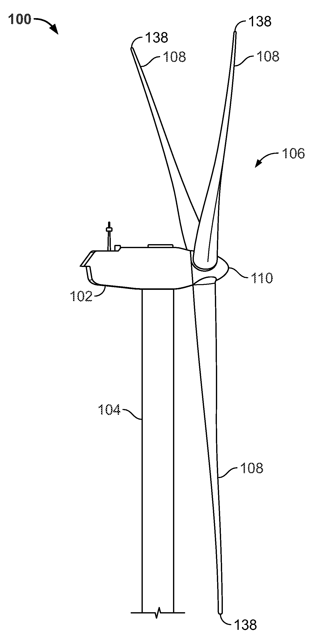
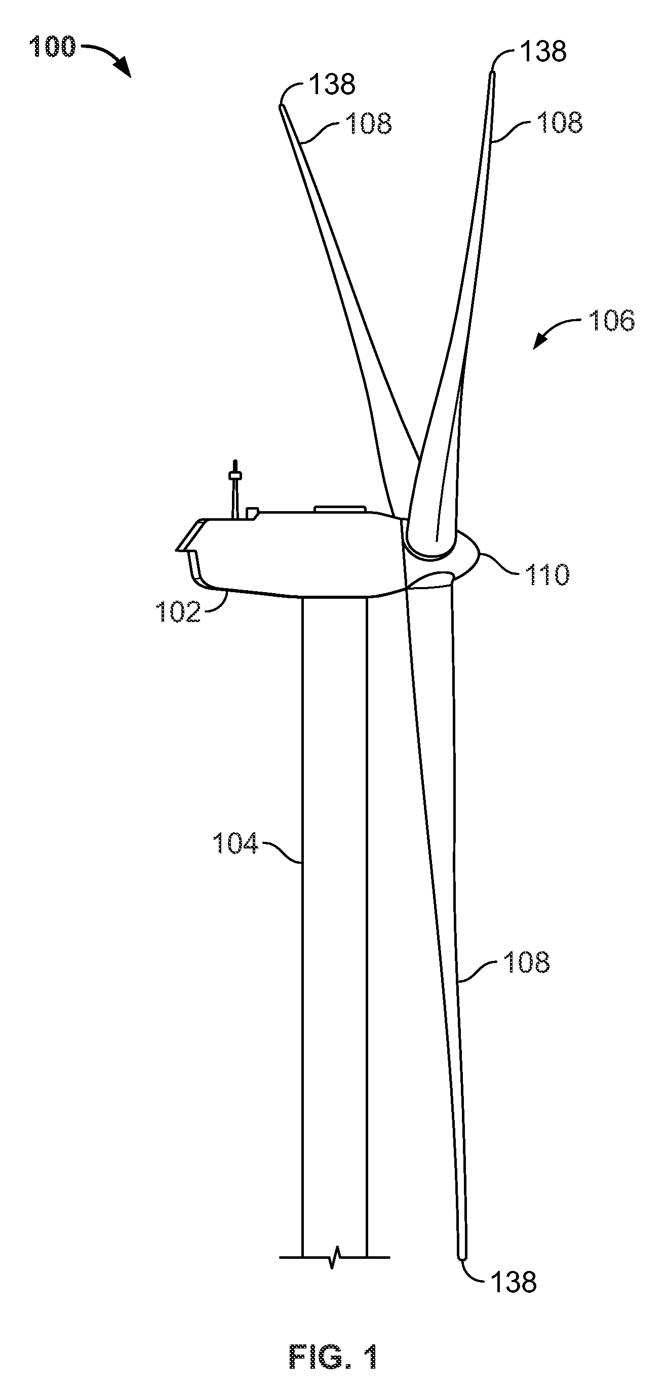
[0043]Referring to FIG. 1, an exemplary wind turbine 100 according to the present disclosure is disclosed. The wind turbine 100 includes a nacelle 102 mounted atop a tall tower 104, only a portion of which is shown in FIG. 1. Wind turbine 100 also includes a wind turbine rotor 106 that includes one or more rotor blades 108 with blade tips 138 attached to a rotating hub 110. In this exemplary embodiment, wind turbine 100 includes three rotor blades 138. In another embodiment, the wind turbine 100 may include one or more rotor blades 108. In yet another embodiment, there are no specific limits on the number of rotor blades 108.

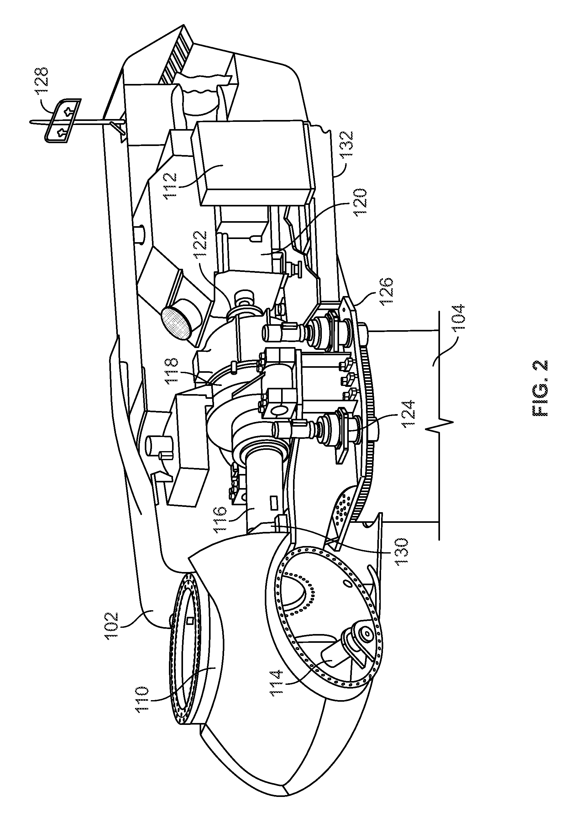
[0044]In some configurations and referring to FIG. 2, an exemplary configuration of various components that are housed in nacelle 102 atop tower 104 are shown. One or more microcontrollers (not shown) are housed within control panel 112. The microcontrollers include hardware and software configured to provide a control system providing overall system monitoring ...


PUM


Abstract

A wind turbine is disclosed that includes a spaceframe mounted atop a support structure. The spaceframe houses and is integrated with a wind turbine drivetrain. The spaceframe transfers primary rotor loads and drivetrain torque to the support structure.

Description

FIELD OF THE DISCLOSURE[0001]The disclosure is generally directed to a wind turbine structure, and more particularly to a compact drivetrain and nacelle including a space-frame for use in wind turbine generators.BACKGROUND OF THE DISCLOSURE[0002]Recently, wind turbines have received increased attention as environmentally safe and relatively inexpensive alternative energy sources. With this growing interest, considerable efforts have been made to develop wind turbines that are reliable and efficient.[0003]Generally, a wind turbine includes a rotor having multiple blades. The blades are attached to a rotatable hub on the rotor. The blades transform mechanical wind energy into a mechanical rotational torque that drives one or more generators. The generators are generally, but not always, rotationally coupled to the rotor through a gearbox. The gearbox steps up the low rotational speed of the turbine rotor for the generator to efficiently convert the rotational mechanical energy to elec...

Claims


Application Information

Patent Timeline
Patent Type & Authority Applications(United States)
IPC IPC(8): F03D11/00E04H12/00
CPCF03D11/00F03D11/04F05B2230/50Y02E10/728Y02B10/30Y02E10/726F05B2240/14F03D80/00F03D13/20F03D80/70F03D15/10F03D80/88Y02E10/72Y02P70/50
Inventor WILLEY, LAWRENCE DONALD
Owner GENERAL ELECTRIC CO
Why Eureka
Try Eureka