Transfer unit and image forming apparatus employing the transfer unit
a transfer unit and image forming technology, applied in the direction of electrographic process apparatus, instruments, optics, etc., can solve the problems of preventing the recent market demand for more compact image forming apparatuses, image failure, and expansion of the need for the belt member, so as to improve the cleaning capability and reduce size and cost.
- Summary
- Abstract
- Description
- Claims
- Application Information
AI Technical Summary
Benefits of technology
Problems solved by technology
Method used
Image

Examples
configuration example 1
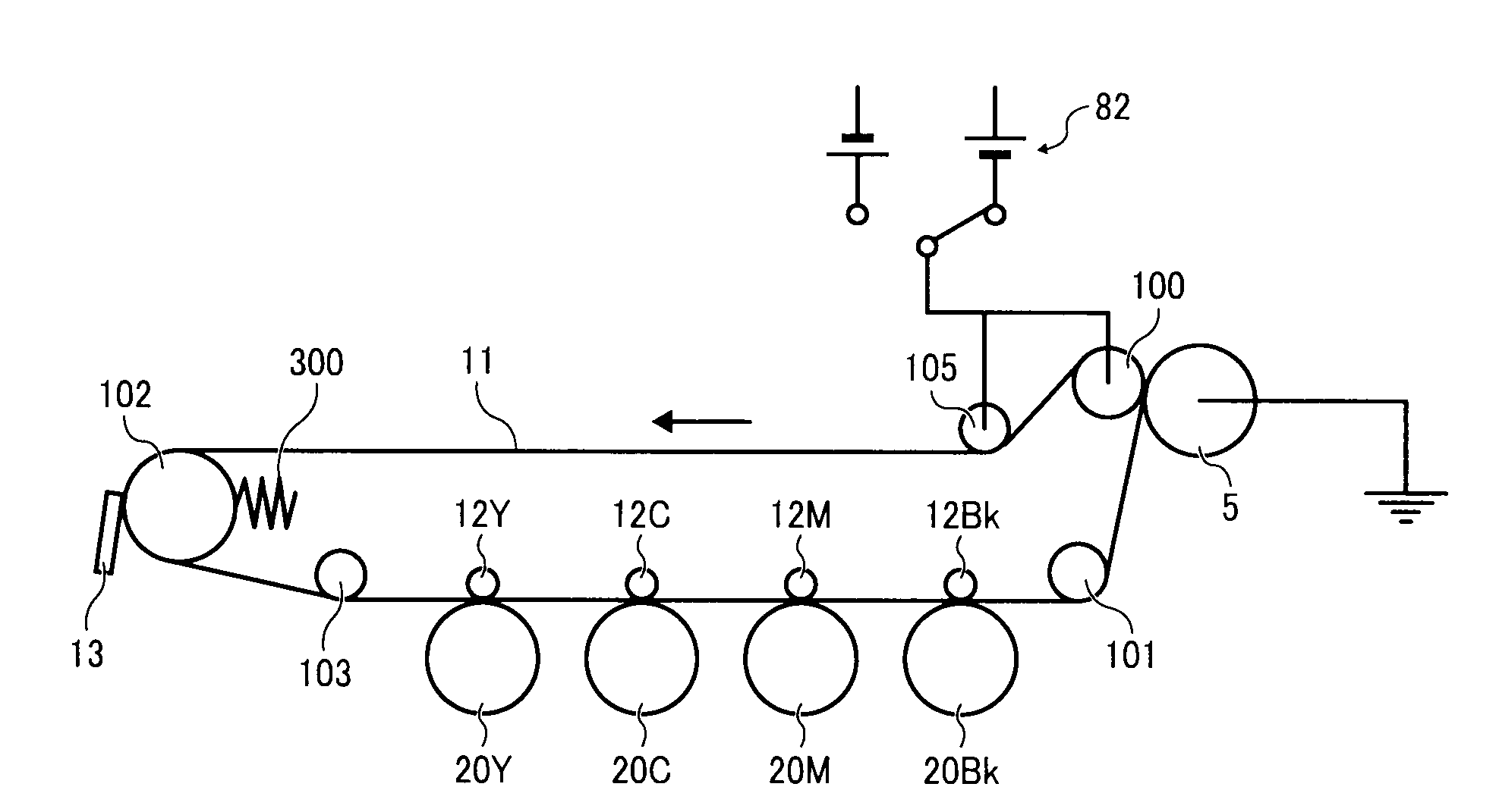
[0066]When cleaning is performed on the secondary transfer roller 5, it is necessary to clean the surface of the secondary transfer roller 5 for one full turn or more by rotating the secondary transfer roller 5 one full turn or more. If the surface of the secondary transfer roller 5 is cleaned for less than one full turn, a portion of the surface of the secondary transfer roller 5 might remain uncleaned. In such a case, residual toner might be adhered to such an uncleaned portion and then to a back face (a sheet face facing the secondary transfer roller 5) of the recording sheet P fed into the transfer nip.
[0067]In the present configuration example, the diameter of the surface roller 105 is smaller than the diameter of the secondary transfer roller 5. In other words, the circumferential length L2 of the surface roller 105 is shorter than the circumferential length L1 of the secondary transfer roller 5. Further, the surface moving speed of the intermediate transfer belt 11, that is, ...
configuration example 2
[0072]In this configuration example, in addition to the configuration described in Configuration Example 1, the relation between the circumferential length L1 of the secondary transfer roller 5 and the circumferential length L2 of the surface roller 105 satisfies the following Formula 2.
L1=L2×n(where “n” is an integer of one or more)
[0073]In other words, the circumferential length L1 of the secondary transfer roller 5 is set to an integral multiple of the circumferential length L2 of the surface roller 105.
[0074]Further, in this example, the surface moving speed of the intermediate transfer belt 11, i.e., the rotation speed of the surface roller 105 is set equal to the rotation speed of the secondary transfer roller 5. The secondary transfer roller 5 is configured to rotate in conjunction with the surface movement of the intermediate transfer belt 11.
[0075]As described above, on cleaning the secondary transfer roller 5 or the surface roller 105, the power supply 82 applies a posi...
configuration example 3
>
[0077]In this example, in addition to the configuration described in Configuration Example 1, when cleaning is performed on the secondary transfer roller 5 and the surface roller 105, the surface moving distance D1 in which the secondary transfer roller 5 moves while the power supply 82 supplies a bias to the secondary transfer roller 5 and the surface roller 105 is set to satisfy the following Formula 3.
D1=L1×n(where “n” is an integer of two or more)
[0078]In this example, the time period during which the power supply 82 supplies a bias to the driving roller 100 and the surface roller 105 in cleaning the driving roller 100 and the surface roller 105 is set to a time period during which the secondary transfer roller 5 rotates two full turns. In such a case, since the secondary transfer roller 5 having the circumferential length L1 rotates two full turns during the time period, n=2 is substituted into Formula 3. As a result, the surface moving distance D1 of the secondary transfer...
PUM
 Abstract
Description
Claims
Application Information
PatSnap Eureka turns technology decisions into work you can execute. Powered by our Innovation Knowledge Graph, it runs expert workflows across engineering, life sciences, materials and intellectual property. Get your review-ready output in minutes.


