Microfluidic device, sample analyzing method using the same, and dilution ratio measuring method

a microfluidic device and sample analysis technology, applied in the direction of positive displacement liquid engines, laboratory glassware, instruments, etc., can solve the problems of difficult for even a skilled clinical pathologist to perform various examinations at the same time, and the need for rapid examination results

Inactive Publication Date: 2010-01-14
SAMSUNG ELECTRONICS CO LTD
View PDF3 Cites 24 Cited by
  • Summary
  • Abstract
  • Description
  • Claims
  • Application Information

AI Technical Summary

Benefits of technology

[0028]According to another aspect of one or more exemplary embodiments, there is provided a method of measuring dilution ratios comprising: loading a sample and a sample diluent into first and second concentration detecting chambers; detecting light absorption values of the sample and the sample diluent,...

Problems solved by technology

However, these methods require many manual operations and various devices.
However, such repeated manual processes may produce erroneous results due to “human error.”
However, it can be difficult for even a skilled clinical pathologist to perform various examinations at the same time.
Even more serious, rapid examination results are necessary for immediate treatment of emergency patients.
Conventional pathological exam...

Method used


Image

  • Microfluidic device, sample analyzing method using the same, and dilution ratio measuring method
  • Microfluidic device, sample analyzing method using the same, and dilution ratio measuring method
  • Microfluidic device, sample analyzing method using the same, and dilution ratio measuring method

Examples


Embodiment Construction

[0034]Reference will now be made in detail to exemplary embodiments, examples of which are illustrated in the accompanying drawings, wherein like reference numerals refer to the like elements throughout. In this regard, the present invention may be embodied in many different forms and should not be construed as being limited to the exemplary embodiments set forth herein. Accordingly, exemplary embodiments are merely described below, by referring to the figures, to explain aspects of the present invention.

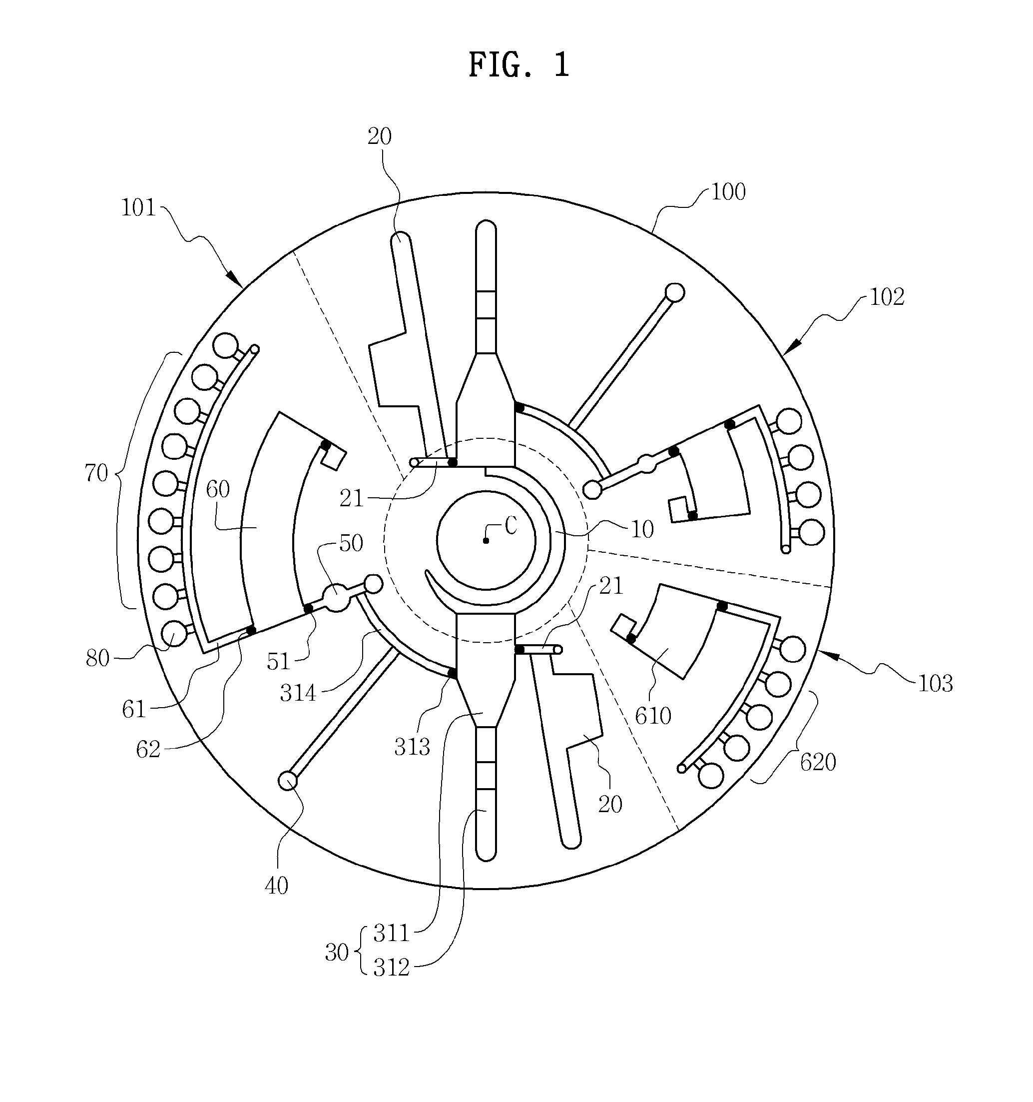
[0035]FIG. 1 illustrates a microfluidic device according to an exemplary embodiment. The microfluidic device includes a rotatable platform 100, for example, a disk-shaped platform, and microfluidic structures that provide space to accommodate fluid or channels through which the fluid can flow in the platform 100. The platform 100 is rotatable around a center C. That is, the microfluidic device can be mounted on and rotated by a rotation driving unit 510 of an analyzer (see FIG. 4). ...


PUM


Abstract

Provided are a microfluidic device, a method of analyzing a sample using the microfluidic device, and a method of measuring dilution ratios. The microfluidic device includes: a sample chamber which accommodates a sample to be tested; a dilution chamber which accommodates a diluent, receives the sample from the sample chamber, and provides a sample diluent; a first concentration detecting chamber which receives the sample from the sample chamber; and a second concentration detecting chamber which receives the sample diluent from the dilution chamber.

Description

CROSS-REFERENCE TO RELATED APPLICATIONS[0001]This application claims priority from Korean Patent Application No. 10-2008-0068343, filed on Jul. 14, 2008 in the Korean Intellectual Property Office, the disclosure of which is incorporated herein in its entirety by reference.BACKGROUND[0002]1. Field[0003]One or more exemplary embodiments of the inventive concept relate to a microfluidic device comprising a microfluidic structure, a method of analyzing samples using the microfluidic device, and a method of measuring dilution ratios.[0004]2. Description of the Related Art[0005]Various methods of analyzing samples have been developed to, for example, monitor environments, examine food, or diagnose the medical condition of a patient. However, these methods require many manual operations and various devices. To perform an examination according to a predetermined protocol, those skilled in the manual operations repeatedly perform various processes including loading of a reagent, mixing, isol...

Claims


Application Information

Patent Timeline
IPC IPC(8): G01N21/00G01N33/00G01N1/38
CPCB01F11/0002Y10T436/2575B01F15/0201B01F15/0205B01F15/021B01F15/0233B01L3/5027B01L3/502738B01L3/502753B01L2300/0806B01L2300/0867B01L2300/087B01L2400/0409B01L2400/0677B01F13/0059B01F31/10B01F33/30B01F35/7135B01F35/713B01F35/71725B01F35/71G01N35/00G01N37/00G01N21/31
Inventor CHO, YOON-KYOUNGLEE, YANG-UI
Owner SAMSUNG ELECTRONICS CO LTD
Why Eureka
Try Eureka