
Actomatic flush actuation apparatus

a technology of flush actuation and actuator, which is applied in the direction of valve operation, water supply installation, transportation and packaging, etc., can solve the problems of failure to operate the flush valve, the structure design of the solenoid operated automatic flush valve is different from that of the manual operation flush valve, and the maintenance cost of the solenoid operated automatic flush valve is higher than that of the conventional manual operation flush valve. , to achieve the effect of avoiding water damage, reducing maintenance costs, and easy installation and maintenan

Active Publication Date: 2010-01-21
MAERCOVICH JORGE
View PDF9 Cites 4 Cited by
  • Summary
  • Abstract
  • Description
  • Claims
  • Application Information

AI Technical Summary

Benefits of technology

[0020]Another object of the present invention is to provide the method for controlling the volume of water, wherein the toilet mode further has a high volume toilet mode and a low volume toilet mode. The high volume toilet mode is configured with relatively higher volume of water in responsive to longer time duration of presence, and the lower volume toilet mode is responsive to shorter time duration of presence.
[0031]Another object of the present invention is to provide an automatic flush actuation apparatus, which provides an economic and efficient solution for incorporating with the conventional manual operated flushing system in a simple and economical way.

Problems solved by technology

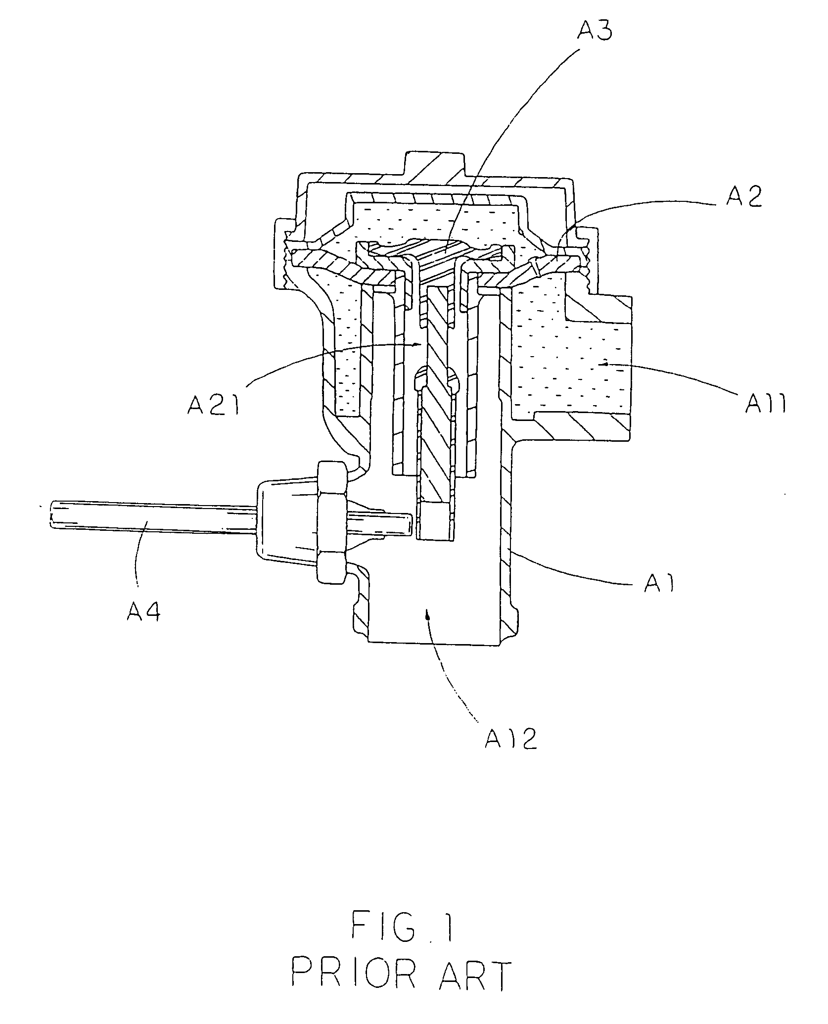
However, the flush valves, according to the above patents, have several common drawbacks.
It is one of the common problems to cause a failure of operation of the flush valve.
Thus, the maintenance cost of the solenoid operated automatic flush valve is higher than that of the conventional manual operated flush valve.
In addition, the structural design of the solenoid operated automatic flush valve is different from that of the manual operated flush valve.
In other words, when the flushing system is incorporated with the solenoid operated automatic flush valve, the flushing system will lose the mechanical-manual operated feature.
Therefore, there is no alternative to operate the flushing cycle when the solenoid operated automatic flush valve has failed to operate.
In order to install the solenoid operated automatic flush valve into the conventional flushing system, the mechanical-manual operating mechanism of the flush valve must be totally removed, which is a waste of resources in order to incorporated with the solenoid operated automatic flush valve.
The configuration of the solenoid operated automatic flush valve is complicated, wherein once the solenoid is broken or the battery is dead, the facility should call a technician to open an outer cover and disassemble an inner cover for the replacement of the solenoid or the battery.
Due to the complicated structure of the solenoid operated automatic flush valve, the solenoid operated automatic flush valve requires a skilled technician to replace the broken solenoid and / or even replace the battery, which may further increase the maintenance cost of the infrared operated automatic flush valve.

Method used


Image

  • Actomatic flush actuation apparatus
  • Actomatic flush actuation apparatus
  • Actomatic flush actuation apparatus

Examples


Embodiment Construction

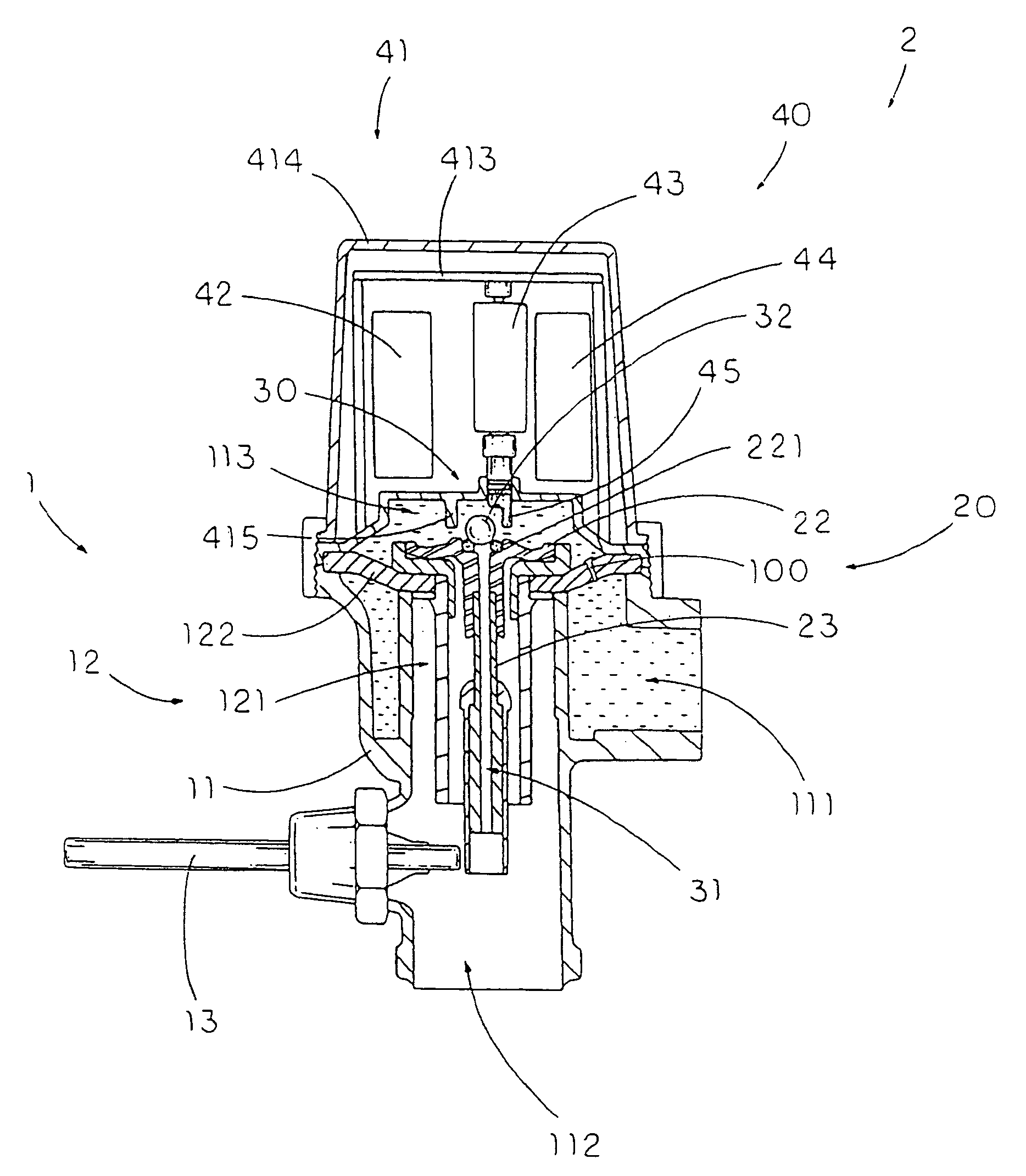
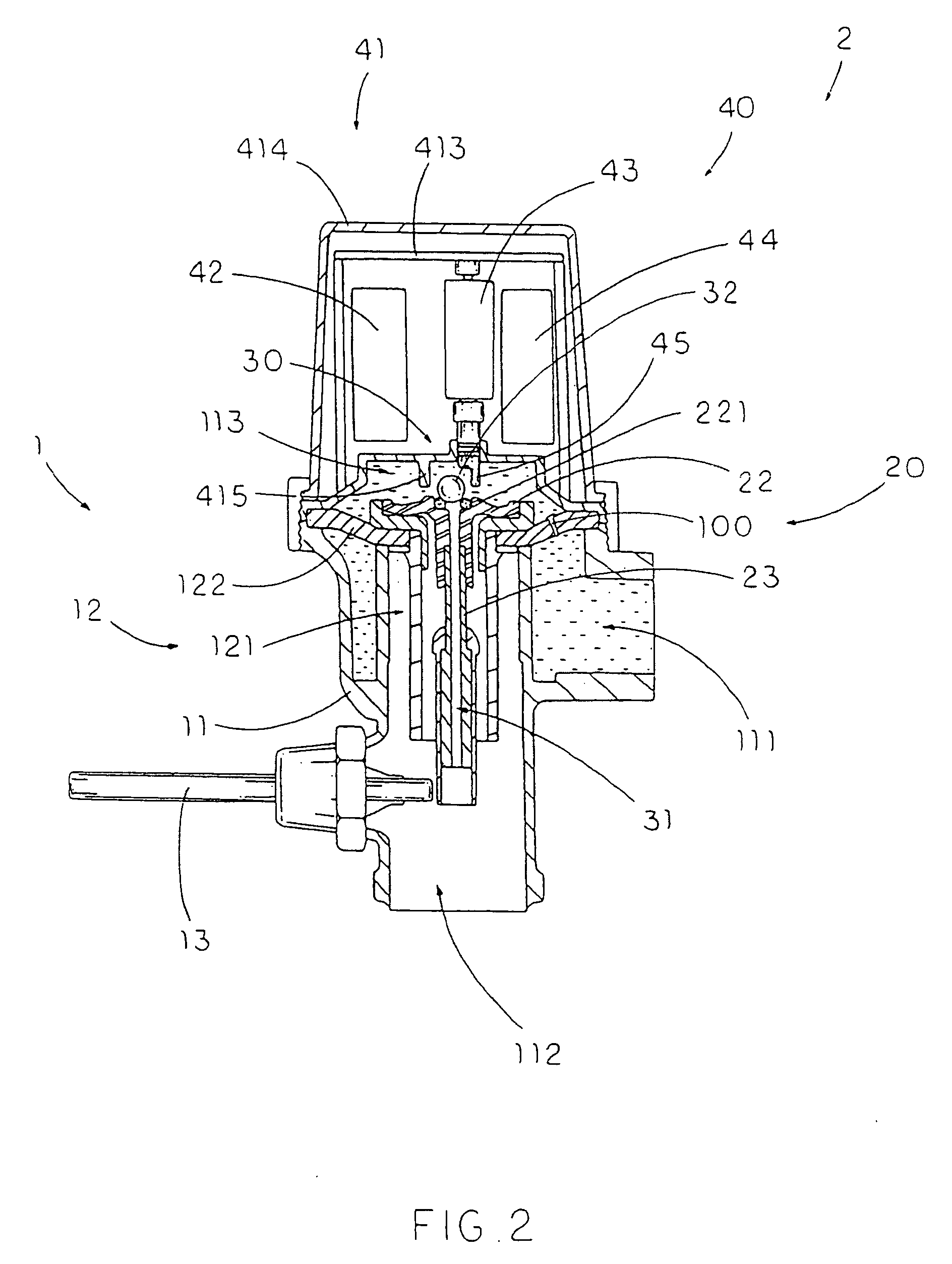
[0054]Referring to FIG. 2 of the drawings, an automatic flush actuation apparatus 2 for a flushing system 1 according to a preferred embodiment of the present invention is illustrated, wherein the automatic flush actuation apparatus 2 is capable of incorporating with a conventional manual operated fluid flow system such as a flushing system to achieve both manual and automatic operations to start a flushing cycle of the flushing system 1.

[0055]The flushing system 1, such as the conventional manual operated flushing system, comprises a valve body 11 having a water inlet 111, a water outlet 112 and a water chamber 113 that is normally sealed between the water inlet 111 and the water outlet 112, a valve seat 12, having a flush channel 121, disposed between the water inlet 111 and the water outlet 112 to block water flowing from the water inlet 111 to the water outlet 112, and a flush lever 13 coupled with the valve body 11.

[0056]The valve seat 12 comprises a diaphragm 122, having a ble...


PUM


Abstract

An automatic flush actuation apparatus, which is incorporated with a flushing system having a water inlet, a water outlet, and a water chamber communicating therebetween, that includes a valve member being moved by a flush lever for releasing the water pressure within the water chamber to allow the water passing from the water inlet to the water outlet, and a sensor-operated powering assembly including a relief valve provided at the valve member for controlling the water flowing to the water outlet and an actuator arranged in such a manner that while sensing a presence of a user of the flushing system, the actuator is driven to move the relief valve to an opened position for releasing the water pressure within the water chamber to allow the water passing to said water outlet.

Description

CROSS REFERENCE OF RELATED APPLICATION[0001]This is a Continuation-In-Part application that claims the benefit of priority under 35 U.S.C. §119 to a non-provisional application having an application Ser. No. 12 / 454,775 and a filing date of May 21, 2009, which is a Continuation application of a non-provisional application having an application Ser. No. 12 / 215,553 and a filing date of Jun. 27, 2008, which is a Continuation application that claims the benefit of priority under 35 U.S.C. §119 to a non-provisional application having an application Ser. No. 11 / 801,928 and a filing date of May 11, 2007, which is a divisional application that claims the benefit of priority under 35 U.S.C. §119 to a non-provisional application, having an application Ser. No. 11 / 192,627 and a filing date of Jul. 29, 2005, which is a divisional application that claims the benefit of priority under 35 U.S.C. §119 to a non-provisional application having an application Ser. No. 11 / 004,704 and a filing date of Dec...

Claims


Application Information

Patent Timeline
Patent Type & Authority Applications(United States)
IPC IPC(8): F15C3/00
CPCE03D3/06F16K31/3855E03D5/10Y10T137/0318
Inventor MAERCOVICH, JORGE
Owner MAERCOVICH JORGE
Learn More