Electrical busway and offset coupling assembly therefor

a technology of offset coupling and electric busway, which is applied in the direction of cable junctions, connection contact material, coupling device connections, etc., can solve the problems of delays in construction process, installation of unplanned obstructions during construction,

Inactive Publication Date: 2010-01-21
EATON CORP
View PDF7 Cites 15 Cited by
  • Summary
  • Abstract
  • Description
  • Claims
  • Application Information

AI Technical Summary

Problems solved by technology

During installation of a busway run, unplanned obstructions are sometimes installed during construction.
Such off

Method used


Image

  • Electrical busway and offset coupling assembly therefor
  • Electrical busway and offset coupling assembly therefor
  • Electrical busway and offset coupling assembly therefor

Examples


Embodiment Construction

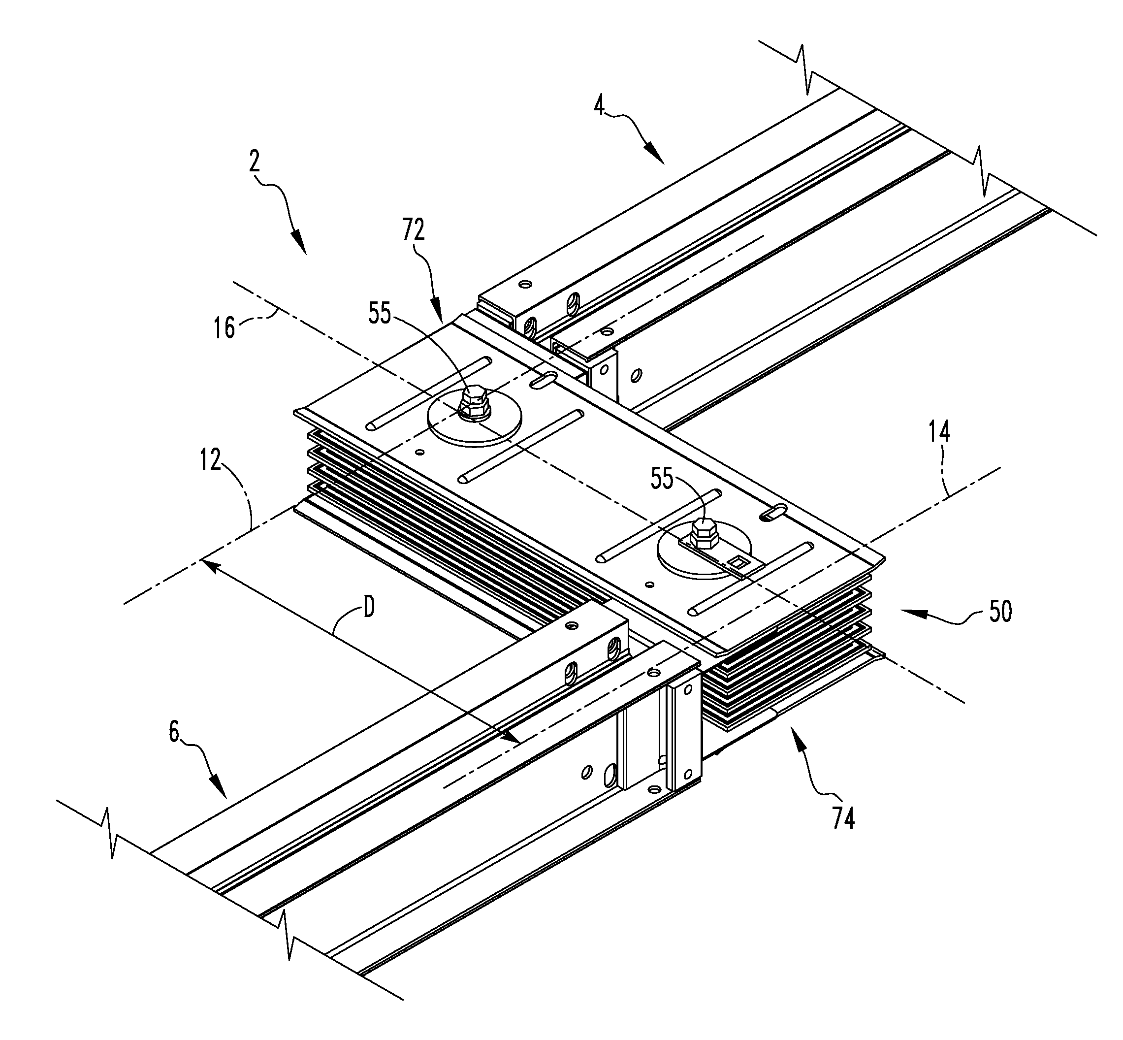
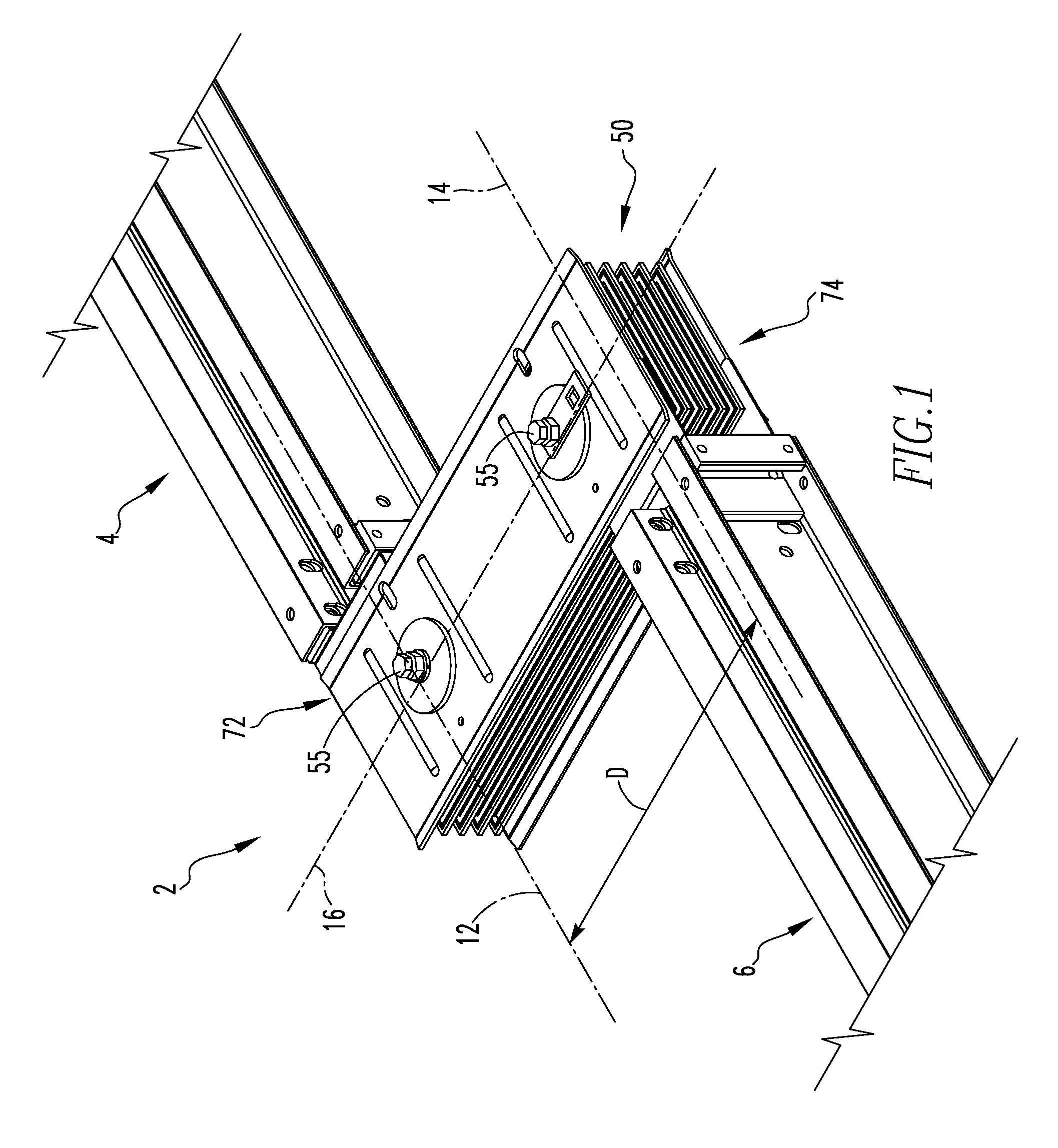
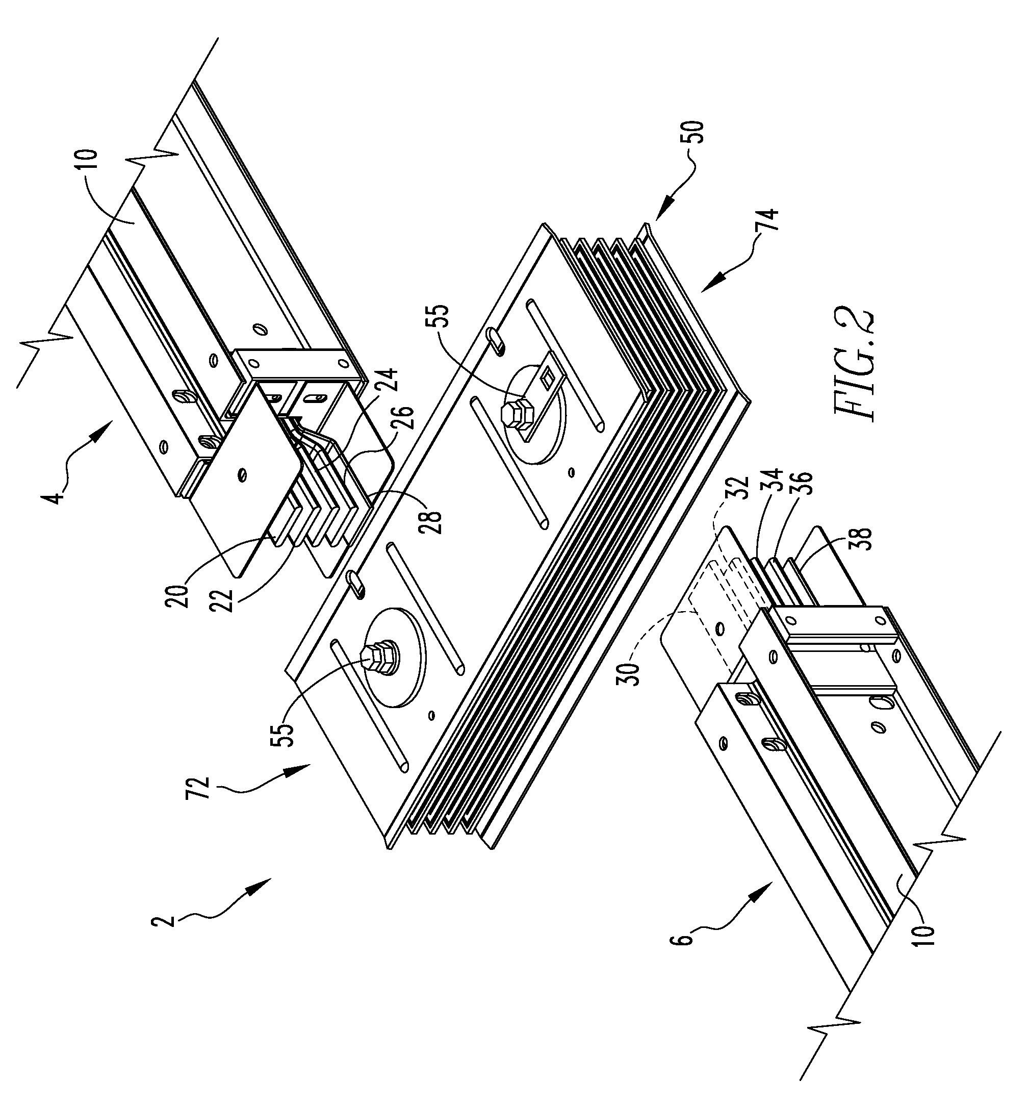
[0024]Directional phrases used herein, such as, for example, left, right, front, back, top, bottom and derivatives thereof, relate to the orientation of the elements shown in the drawings and are not limiting upon the claims unless expressly recited therein.

[0025]As employed herein, the term “electrical busway” refers to an assembly of electrical conductors housed within a supporting structure such as, for example and without limitation, a rail structure. The electrical conductors receive electrical power from, for example, a utility or other suitable power source.

[0026]As employed herein, the term “electrical conductor” means any known or suitable component expressly intended to conduct electrical current. An electrical conductor may be relatively flexible, and expressly includes, but is not limited to, electrical wires and electrical cables.

[0027]As employed herein, the term “bus bar” refers to a substantially rigid (e.g., inflexible) electrical conductor.

[0028]As employed herein,...


PUM


Abstract

A coupling assembly is provided for an electrical busway having a first section and a second section. The coupling assembly includes a plurality of electrical conductors that electrically connect the first and second sections of the electrical busway. A plurality of electrical insulators are positioned to electrically insulate the plurality of electrical conductors. The coupling assembly is structured to offset the first section of electrical busway a predetermined, non-zero distance from the second section of electrical busway.

Description

BACKGROUND OF THE INVENTION[0001]1. Field of the Invention[0002]The invention relates generally to electrical conductors and, more particularly, to electrical busways. The invention also relates to coupling assemblies for electrical busways.[0003]2. Background Information[0004]Various electrical components are defined by, and subject to, regulatory requirements. For example and without limitation, the Underwriter's Laboratory (UL) defines an “electrical busway”, at UL 857, as a grounded metal enclosure containing factory mounted conductors that are usually copper or aluminum bars, rods, or tubes. Similarly, the National Electric Code (NEC) defines an electrical busway as a grounded metal enclosure containing factory mounted, bare, or insulated conductors, which are usually copper or aluminum bars, rods, or tubes.[0005]Typically, electrical busways are comprised of a number of straight sections joined by bridge joints. Each of the busway sections includes a plurality of electrical co...

Claims


Application Information

Patent Timeline
IPC IPC(8): H02G3/06H01R4/60
CPCH02G5/007H01R25/162
Inventor JUR, ARTHUR J.MILLER, PHILLIP D.TAYLOR, DOUGLAS V.
Owner EATON CORP
Why Eureka
Try Eureka