Multi-Layer Piezoelectric Element and Injection Apparatus Using the Same

a piezoelectric element and injection apparatus technology, applied in the direction of machine/engine, device details, device details, etc., can solve the problems of low displacement performance, and achieve the effects of reducing the restrictive force, reducing the strength of the device against breakage and the suppression of insulation, and high reliability

Active Publication Date: 2010-01-21
KYOCERA CORP
View PDF20 Cites 16 Cited by
  • Summary
  • Abstract
  • Description
  • Claims
  • Application Information

AI Technical Summary

Benefits of technology

[0033]The multi-layer piezoelectric element described in (1) makes it possible to decrease the restrictive force of the undisplaceable portion that restricts the displacement of the displacement portion, since at least a part of the peripheral area is formed as the disperse area where a plurality of regions consisting of an inorganic compound are dispersed via voids. Also because the above-mentioned regions are dispersed via the voids in the peripheral area, strength of the device against breakage and the insulation can be suppressed from decreasing. This enables high reliability and high displacement performance to be achieved at the same time. As a result, a large amount of displacement can be maintained even when the number of layers in the stack is made less than that of the prior art, and therefore the multi-layer piezoelectric element can be made more compact. Also a large amount of displacement can be maintained even when the voltage applied is made lower than that of the prior art. Moreover, short-circuiting can be prevented from occurring across electrodes more reliably by decreasing the applied voltage.
[0034]In the present invention, the expression “a plurality of regions consisting of an inorganic compound are dispersed via voids” means that a plurality of the above-mentioned regions are disposed in the state of being isolated from each other via voids between two piezoelectric layers that are disposed adjacently in the stacking direction.
[0035]In the multi-layer piezoelectric element described in (2), the regions consisting of the inorganic compound are metallic regions consisting of a metal, and the disperse area is constituted from the plurality of metallic regions dispersed in the state of being insulated from the internal electrode layer. As the disperse area is constituted from the plurality of dispersed metallic regions that are more pliable than the piezoelectric ceramics that constitutes the piezoelectric layers, the restrictive force of the undisplaceable portion that restricts the displacement of the displacement portion can be decreased. Also because the metallic regions are dispersed via the voids, the contact area between the metallic region and the piezoelectric layer can be decreased, and therefore the force of the metallic regions to clamp the piezoelectric layer can be decreased. While compressive stress and tensile stress are distributed in a complicated manner when the multi-layer piezoelectric element undergoes displacement, the disperse area of the present invention constituted from the plurality of dispersed metallic regions makes it possible for the metallic regions included

Problems solved by technology

However, increasing the peripheral area leads to a problem of lower

Method used


Image

  • Multi-Layer Piezoelectric Element and Injection Apparatus Using the Same
  • Multi-Layer Piezoelectric Element and Injection Apparatus Using the Same
  • Multi-Layer Piezoelectric Element and Injection Apparatus Using the Same

Examples


first embodiment

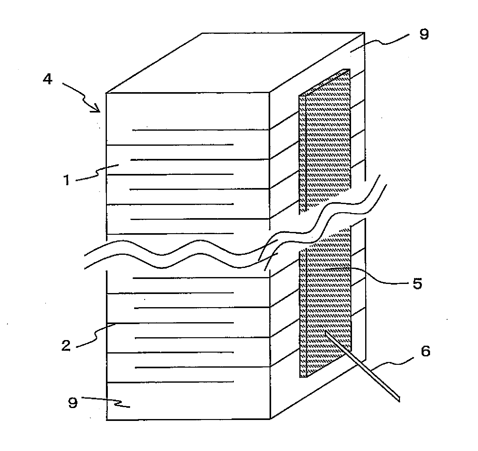
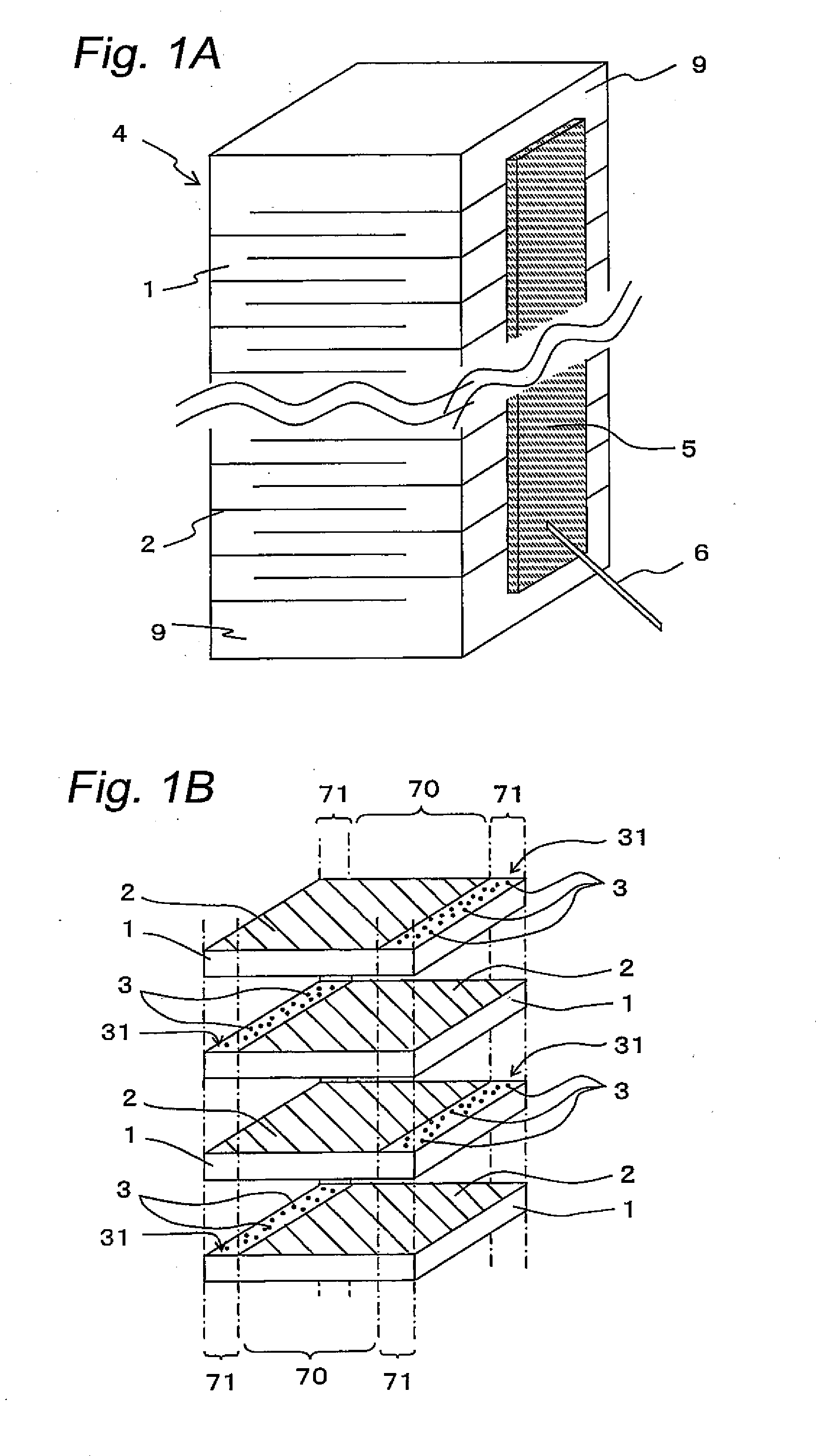
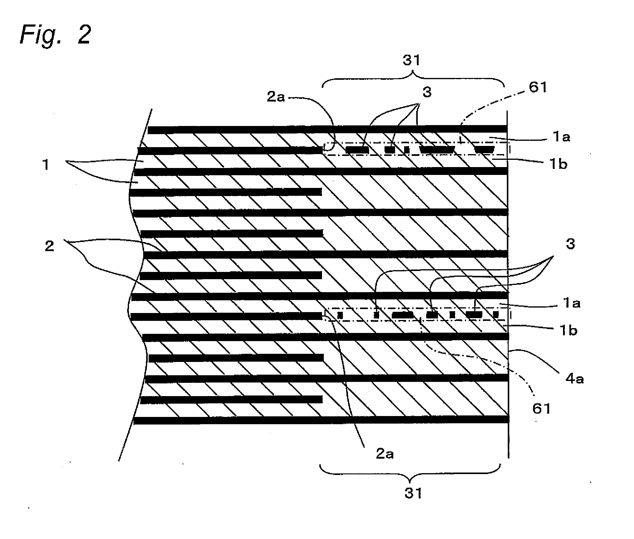
[0082]The multi-layer piezoelectric element according to the first embodiment of the present invention will be described below with reference to the accompanying drawings. FIG. 1A is a perspective view showing the multi-layer piezoelectric element according to this embodiment. FIG. 1B is a partial sectional view showing the state of the piezoelectric layers and the internal electrode layers (metal layers) being stacked in the multi-layer piezoelectric element. FIG. 2 is a partially enlarged sectional view showing the structure of the piezoelectric layers and the internal electrode layers being stacked in the multi-layer piezoelectric element of the first embodiment

[0083]As shown in FIG. 1A and FIG. 1B, the multi-layer piezoelectric element has a stack 4 formed by stacking a plurality of piezoelectric layers 1 via internal electrode layers 2. The stack 4 has, formed on a side face thereof, a pair of external electrodes 5 connected to the plurality of internal electrode layers 2 in ev...

second embodiment

[0101]FIG. 3 is a partial sectional view showing the structure of the piezoelectric layers 1 and the internal electrode layers 2 being stacked in the multi-layer piezoelectric element according to the second embodiment of the present invention. As shown in FIG. 3, the multi-layer piezoelectric element of this embodiment has voids 21 formed between neighboring regions 3, 3 in the disperse area 61. In other words, the disperse area 61 includes the metallic regions 3, that are more pliable to undergo deformation than the piezoelectric ceramics that constitute the piezoelectric layers 1, and the voids 21. The disperse area 61 includes the plurality of metallic regions 3 that are dispersed therein while being insulated from the internal electrode layer 2, and the plurality of voids 21 dispersed therein. There are the voids 21 located between the neighboring metallic regions 3, 3. The existence of the voids 21 between the neighboring metallic regions 3, 3 ensures insulation so that the ne...

third embodiment

[0104]FIG. 4 is a partially enlarged sectional view showing the structure of the piezoelectric layers 1 and the internal electrode layers 2 being stacked in the multi-layer piezoelectric element according to the third embodiment of the present invention. As shown in FIG. 4, the multi-layer piezoelectric element of this embodiment has the disperse area 61 formed in a plurality of peripheral areas 31 (that is, in all peripheral areas 31) located between the edges 2a of all the internal electrode layers 2 and the side faces 4a of the stack 4. FIG. 4 gives an enlarged view of a portion in the vicinity of one side face of the stack 4, without showing the side face that opposes this side face. The disperse areas 61 are formed also in all of the peripheral areas 31 in the vicinity of the opposite side face. This constitution significantly reduces the restrictive force of the undisplaceable portion that restricts the displacement of the displacement portion, thereby greatly improving the di...


PUM


Abstract

To provide a multi-layer piezoelectric element having high strength against breakage, high insulation and excellent displacement performance, and an injection apparatus that incorporates the same.
The multi-layer piezoelectric element comprising a stack 4 constituted from a plurality of piezoelectric layers 1 stacked one on another via internal electrode layers 2, wherein at least a part of peripheral areas 31, that are disposed between two piezoelectric layers 1, 1 located adjacently in the stacking direction and are located between an edge 2a of the internal electrode layer 2 and side face 4a of the stack 4, is disperse areas where a plurality of metallic regions are dispersed via voids 21.

Description

TECHNICAL FIELD[0001]The present invention relates to a multi-layer piezoelectric element and an injection apparatus, and more particularly to a multi-layer piezoelectric element and an injection apparatus used in, for example, a fuel injection apparatus of an automobile engine; a liquid injection apparatus of an ink jet printer or the like; a drive unit for a precision positioning device; a vibration preventing device for an optical apparatus; a sensor element mounted in a combustion pressure sensor, a knocking sensor, an acceleration sensor, a load sensor, an ultrasound sensor, a pressure sensor, a yaw rate sensor or the like; and circuit component mounted in a piezoelectric gyro, a piezoelectric switch, a piezoelectric transducer, a piezoelectric breaker or the like.BACKGROUND ART[0002]Piezoelectric actuators have been known as an application of multi-layer piezoelectric elements that are constituted from a plurality of piezoelectric layers stacked via internal electrode layers (...

Claims


Application Information

Patent Timeline
IPC IPC(8): H01L41/083F02M51/00F02M51/06H01L41/187H01L41/27H01L41/297H02N2/00
CPCF02M51/0603H01L41/0838H01L41/0472H01L41/04H10N30/80H10N30/872H10N30/508
Inventor SHOJI, JUNYAINAGAKI, MASAHIRONAKAMURA, SHIGENOBU
Owner KYOCERA CORP
Why Eureka
Try Eureka