Light emitting device and method for producing same

a light emitting device and light source technology, which is applied in the direction of discharge tube luminescent screen, discharge tube/lamp details, luminescent compositions, etc., can solve the problems of difficult control of the amount of resin to be applied, difficult control of the color temperature of the light emitting device, and color irregularities, etc., to reduce color irregularities, high emission power, and color reproducibility good

Inactive Publication Date: 2010-01-21
DOWA ELECTRONICS MATERIALS CO LTD
View PDF12 Cites 20 Cited by
  • Summary
  • Abstract
  • Description
  • Claims
  • Application Information

AI Technical Summary

Benefits of technology

[0013]It is therefore an object of the present invention to eliminate the aforementioned problems and to provide a light emitting device which has a high emission power, a small irregularity in color and good color rendering properties, and a method for producing the same.
[0014]It is another object of the present invention to eliminate the aforementioned problems and to provide a light emitting device which has a high emission power, a small irregularity in color and good color rendering properties and which can reduce the irregularity in color regardless of the shape of a sealing member, and a method for producing the same.
[0018]In this light emitting device, the difference between the maximum and minimum values of correlated color temperatures is preferably 300K or less. If the difference between the maximum and minimum values of correlated color temperatures is 300K or less, it is possible to further decrease the irregularity in color, so that the light emitting device can be used as a spot illumination device. The large phosphor particles preferably have a particle diameter of not less than 10 μm and of less than 50 μm, and more preferably have a particle diameter of 20 to 40 μm. The small phosphor particles preferably have a particle diameter of not less than 1 μm and of less than 10 μm, and more preferably have a particle diameter of 3 to 8 μm. The light emitting device preferably has a general color rendering index Ra of not less than 90. If the general color rendering index Ra is not less than 90, when an object is irradiated with light emitted from the light emitting device, the color of the object visible by viewers approaches the color of the object visible by viewers when the object is irradiated with sunlight, and the color reproducibility is good, so that the light emitting device is suitable for a light source for illumination.
[0022]In this light emitting device, the difference between the maximum and minimum values of correlated color temperatures is preferably 300K or less. If the difference between the maximum and minimum values of correlated color temperatures is 300K or less, it is possible to further decrease the irregularity in color, so that the light emitting device can be used as a spot illumination device. The large phosphor particles preferably have a particle diameter of not less than 10 μm and of less than 50 μm, and more preferably have a particle diameter of 20 to 40 μm. The small phosphor particles preferably have a particle diameter of not less than 1 μm and of less than 10 μm, and more preferably have a particle diameter of 3 to 8 μm. Preferably, the light emitting element is a light emitting element for emitting light having a peak wavelength in the wavelength range of from 420 nm to less than 490 nm, the large phosphor particles are phosphor particles for emitting light having a peak wavelength in the wavelength range of from 490 nm to less than 590 nm, and the small phosphor particles are phosphor particles for emitting light having a peak wavelength in the wavelength range of from 590 nm to 780 nm. The light emitting device preferably has a general color rendering index Ra of not less than 90. If the general color rendering index Ra is not less than 90, when an object is irradiated with light emitted from the light emitting device, the color of the object visible by viewers approaches the color of the object visible by viewers when the object is irradiated with sunlight, and the color reproducibility is good, so that the light emitting device is suitable for a light source for illumination.
[0023]According to the present invention, it is possible to produce a light emitting device which has a high emission power, a small irregularity in color and good color rendering properties. It is also possible to produce a light emitting device which has a high emission power, a small irregularity in color and good color rendering properties and which can reduce the irregularity in color regardless of the shape of a sealing member.

Problems solved by technology

However, if a resin mixed with large phosphor particles is cured, the phosphor particles are easily precipitated in the resin while the resin is cured, so that the variation in amount of the phosphor particles is caused in the resin.
If a resin having a high viscosity is applied by means of a dispenser or the like, it is difficult to discharge the resin from a nozzle, so that it is difficult to control the amount of the resin to be applied.
Therefore, there is a problem in that it is difficult to control the color temperature of the light emitting device.
However, if the particle diameter of the phosphor particles decreases, the light-transforming efficiency generally deteriorates, so that there is a problem in that the emission power of the produced white light emitting device is deteriorated.
However, when the light emitting element arranged in the cup-shaped recessed portion is sealed with a resin by potting, it is not easy to control the shape of a sealing member of the resin so that the optical path length, by which light emitted from the light emitting element passes through the resin, is constant, due to the viscosity of the used resin and the gravity applied to the resin.
As a result, the irregular color of light from the light emitting device is caused.

Method used


Image

  • Light emitting device and method for producing same
  • Light emitting device and method for producing same
  • Light emitting device and method for producing same

Examples


first preferred embodiment

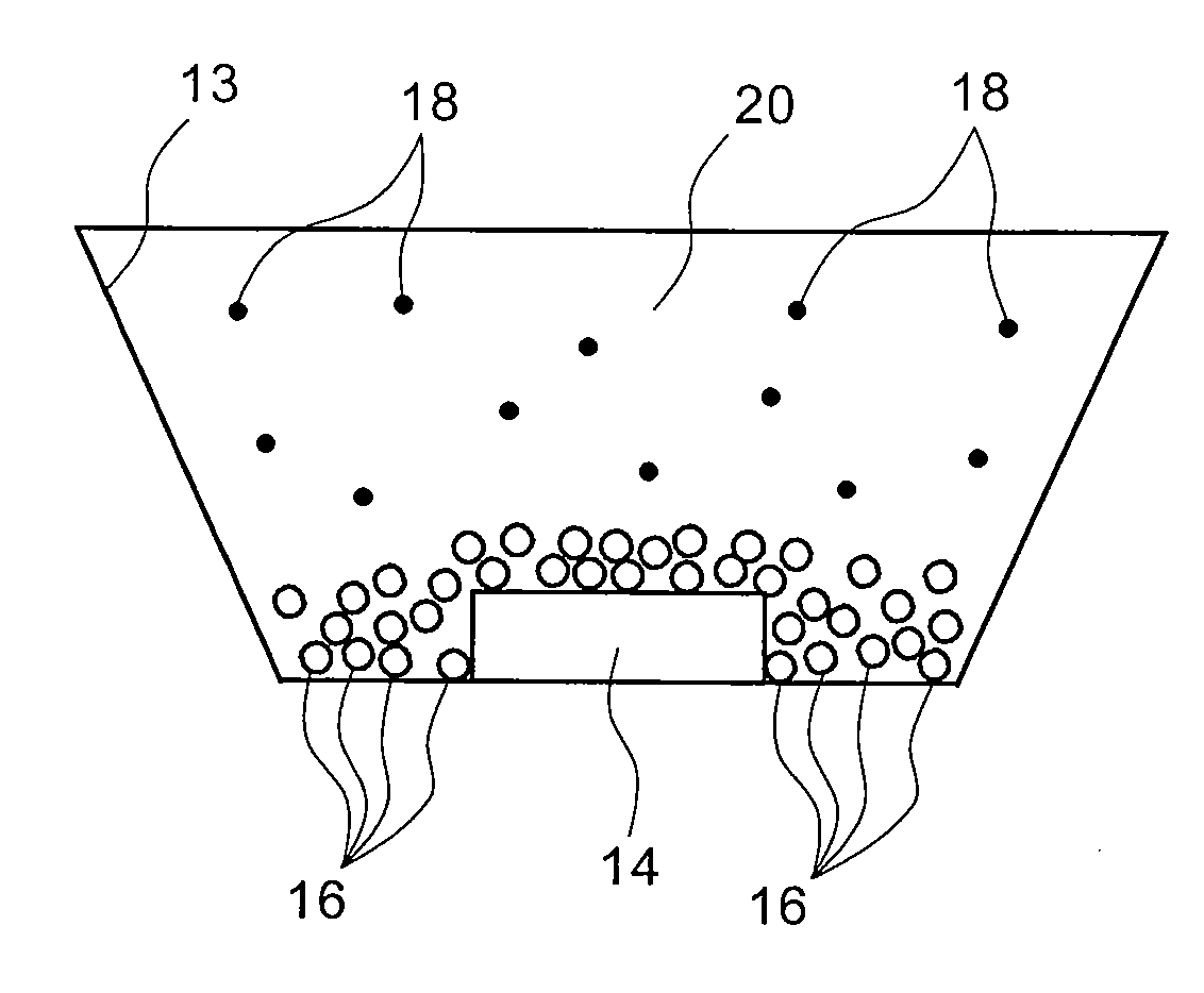
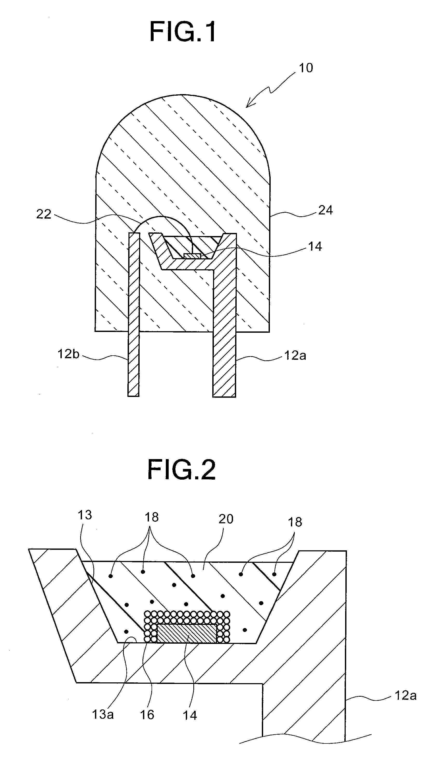
[0048]FIG. 1 is a sectional view schematically showing the first preferred embodiment of a light emitting device according to the present invention, and FIG. 2 is an enlarged sectional view of a cup portion of one of a pair of lead frames, on which a light emitting element of the light emitting device of FIG. 1 is mounted. As shown in FIGS. 1 and 2, the light emitting device 10 in this preferred embodiment comprises: a pair of lead frames 12a and 12b arranged at an interval; a light emitting element 14 which is mounted on the bottom face 13a of a cup (recessed portion) 13 formed in the tip end portion of one lead frame 12a; large phosphor particles 16 which are arranged so as to cover the surface of the light emitting element 14; a sealing member 20 containing small phosphor particles 18, which is filled in the cup 13 of the lead frame 12a so as to cover the large phosphor particles 16; and a transparent mold member 24 which covers the tip end portions of the lead frames 12a and 12b...

second preferred embodiment

[0061]Since a light emitting device and a method for producing the same in the second preferred embodiment are substantially the same as those in the first preferred embodiment, except for the preferred materials of the large phosphor particles 16 and small phosphor particles 18, the duplicate descriptions thereof are omitted.

[0062]Although the large phosphor particles 16 and the small phosphor particles 18 may be made of the same material or different materials, they may be made of such materials that light observed from the outside becomes white light if they are combined with the light emitting element 14.

[0063]Furthermore, if a resin material is used as the material of the sealing member 20, it is difficult for the phosphor particles to be precipitated, so that it is possible to prevent irregular color due to the precipitation of the phosphor particles in the resin, since the phosphor particles to be dispersed in the resin are the small phosphor particles 18.

[0064]Examples of a ...


PUM


Abstract

A light emitting device 10 includes: a lead frame 12a serving as a mounting portion having a cup 13; a light emitting element 14, mounted on the bottom face 13a of the cup, for emitting light having a predetermined peak wavelength; a layer of large phosphor particles 16, absorbed and formed on the light emitting element, for absorbing light emitted from the light emitting element and for emitting light having a longer peak wavelength than that of the light emitted from the light emitting element; small phosphor particles 18, which have a smaller particle diameter than that of the large phosphor particles, for absorbing at least one of light emitted from the large phosphor particles and light emitted from the light emitting element and for emitting light having a longer peak wavelength than that of the at least one of the light emitted from the large phosphor particles and the light emitted from the light emitting element; and a sealing member 20, in which the small phosphor particles are dispersed, for sealing the light emitting element and the layer of large phosphor particles in the cup.

Description

BACKGROUND OF THE INVENTION[0001]1. Field of the Invention[0002]The present invention generally relates to a light emitting device and a method for producing the same. More specifically, the invention relates to a light emitting device wherein a light emitting element is combined with a phosphor (or a fluorescent substance) which is designed to receive light from the light emitting element to emit light having a different wavelength from that of the light emitted from the light emitting element, and a method for producing the same.[0003]2. Description of the Prior Art[0004]In recent years, there has been actively developed a light emitting device for emitting white light by combining a light emitting element, such as a light emitting diode (LED) for emitting light in wavelength ranges from near ultraviolet to blue, with a phosphor (or a fluorescent substance) which is designed to receive light from the light emitting element to emit light having a different wavelength from that of t...

Claims


Application Information

Patent Timeline
Patent Type & Authority Applications(United States)
IPC IPC(8): H01J1/62
CPCC09K11/0883C09K11/7721H05B33/20H05B33/14C09K11/7734H01L2224/48247H01L2224/48091C09K11/77214C09K11/77348H01L2924/00014
Inventor MARUYAMA, TSUKASAGOTOH, MASAHIROIKUTA, TETSUYA
Owner DOWA ELECTRONICS MATERIALS CO LTD
Why Eureka
Try Eureka