Holographic image display system
- Summary
- Abstract
- Description
- Claims
- Application Information
AI Technical Summary
Benefits of technology
Problems solved by technology
Method used
Image

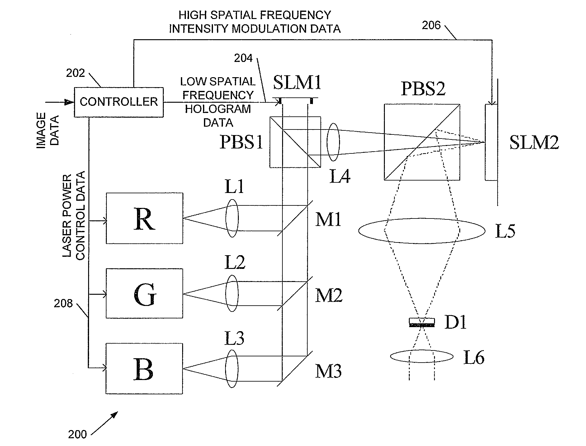
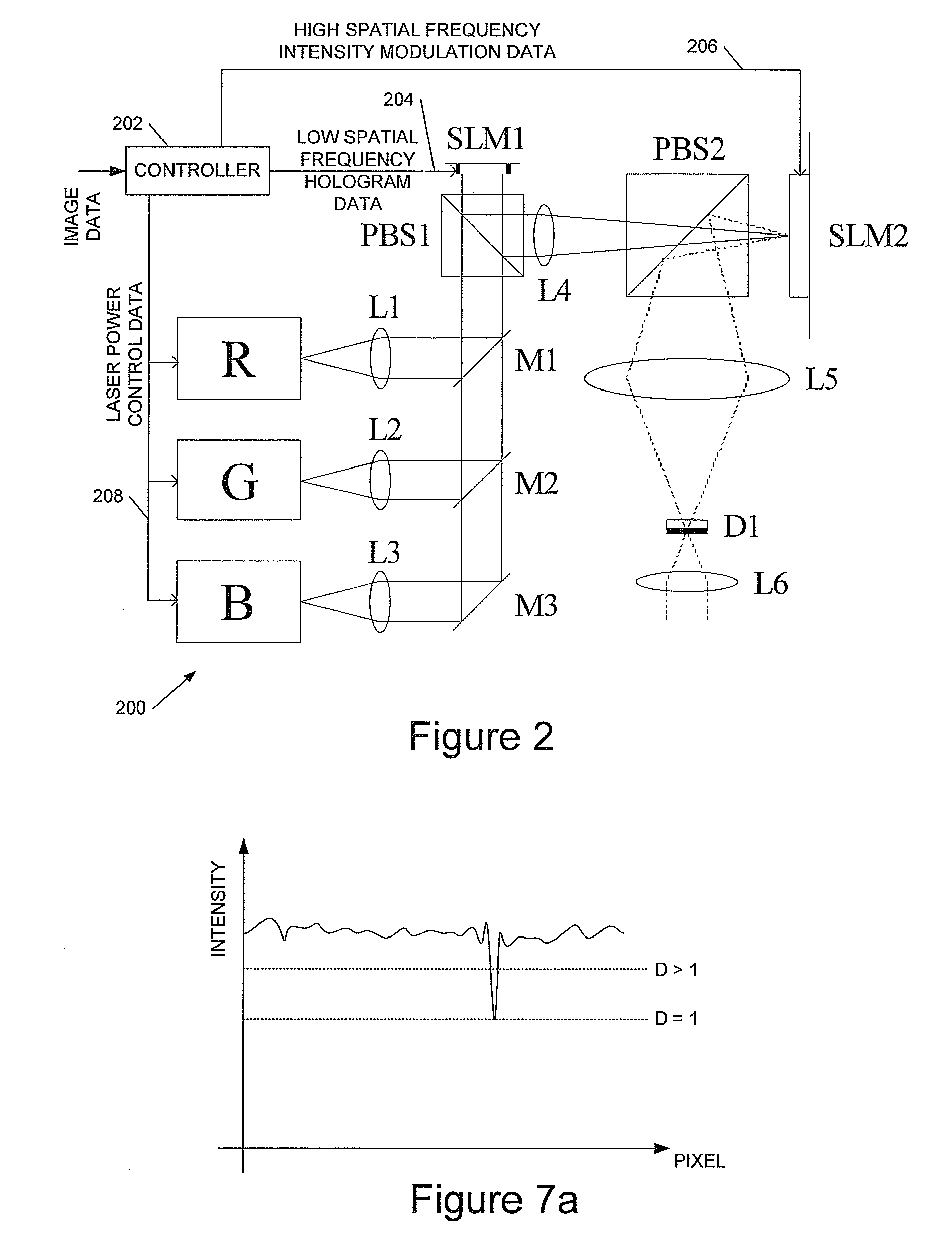
Examples
example procedure
[0138
[0139]We now describe an example procedure to implement embodiments of the invention. This example procedure is based on super-resolution ADOSPR but approaches based, for example, on ADOSPR and on sub-segment ADOSPR may also be employed. In general the techniques are not limited to use with an OSPR-type hologram generation procedure, although this is computationally efficient. The procedure assumes a fast phase-modulating (binary or multi-phase) hologram SLM, and a (slower) nematic imaging SLM, although the skilled person will appreciate that other imaging technologies may be equally appropriate.
[0140]In all cases the illumination incident on the SLM is assumed to be Gaussian, with the 1 / e2 intensity at the edges of the SLM.
[0141]Variables[0142]1. The hologram SLM size is M×M pixels.[0143]2. The input image target amplitude, T, is of size P×P pixels. Amplitude range for the input is between 0 (black) and 1 (white).[0144]3. N ADOSPR subframes are to be generated.[0145]4. D is a ...
PUM
 Abstract
Description
Claims
Application Information
PatSnap Eureka turns technology decisions into work you can execute. Powered by our Innovation Knowledge Graph, it runs expert workflows across engineering, life sciences, materials and intellectual property. Get your review-ready output in minutes.


