Eureka AIR delivers breakthrough ideas for toughest innovation challenges, trusted by R&D personnel around the world.

Holographic image display system

a display system and holographic technology, applied in the field of holographic image display systems, can solve the problems of increasing cost, making miniaturisation difficult, increasing cost, etc., and achieve the effect of increasing the optical (diffraction) efficiency of the system

Active Publication Date: 2011-12-13
DUALITAS LTD
View PDF5 Cites 9 Cited by
  • Summary
  • Abstract
  • Description
  • Claims
  • Application Information

AI Technical Summary

Benefits of technology

[0009]In embodiments of the method the resolution of an SLM displaying the hologram may be relatively low (lower than that of an SLM intensity modulating the intermediate real image), and therefore computation of the hologram becomes straightforward, especially when using an OSPR-type approach such as ADOSPR (adaptive OSPR). In a hardware implementation a small, cheap and very low power ASIC (Application Specific Integrated Circuit) may be employed. Simulations have shown that an SLM resolution of 64×64, or even lower, may be sufficient for the hologram.
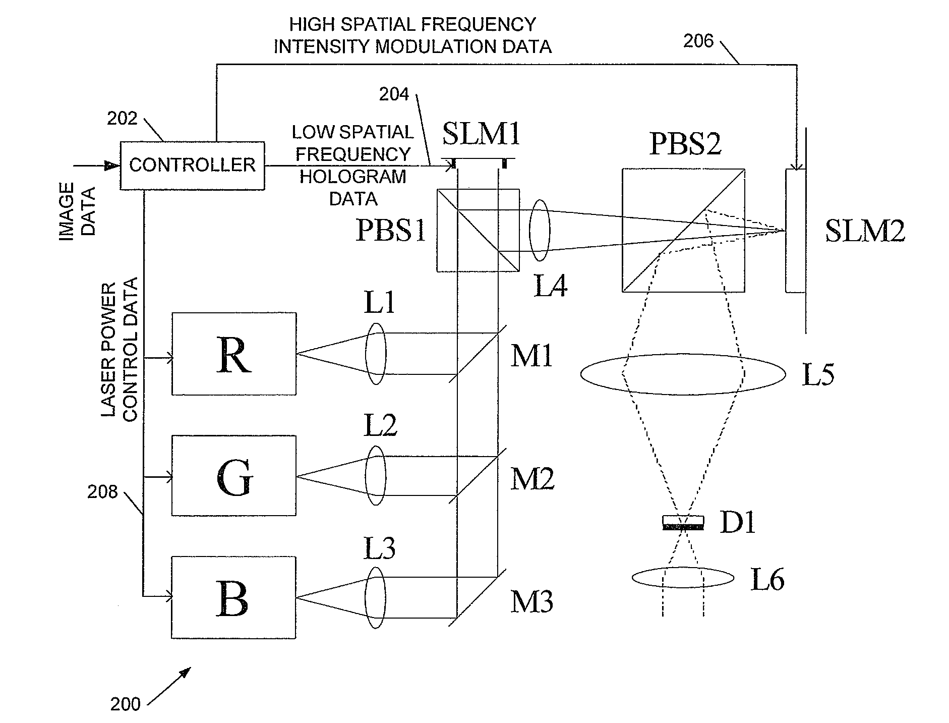
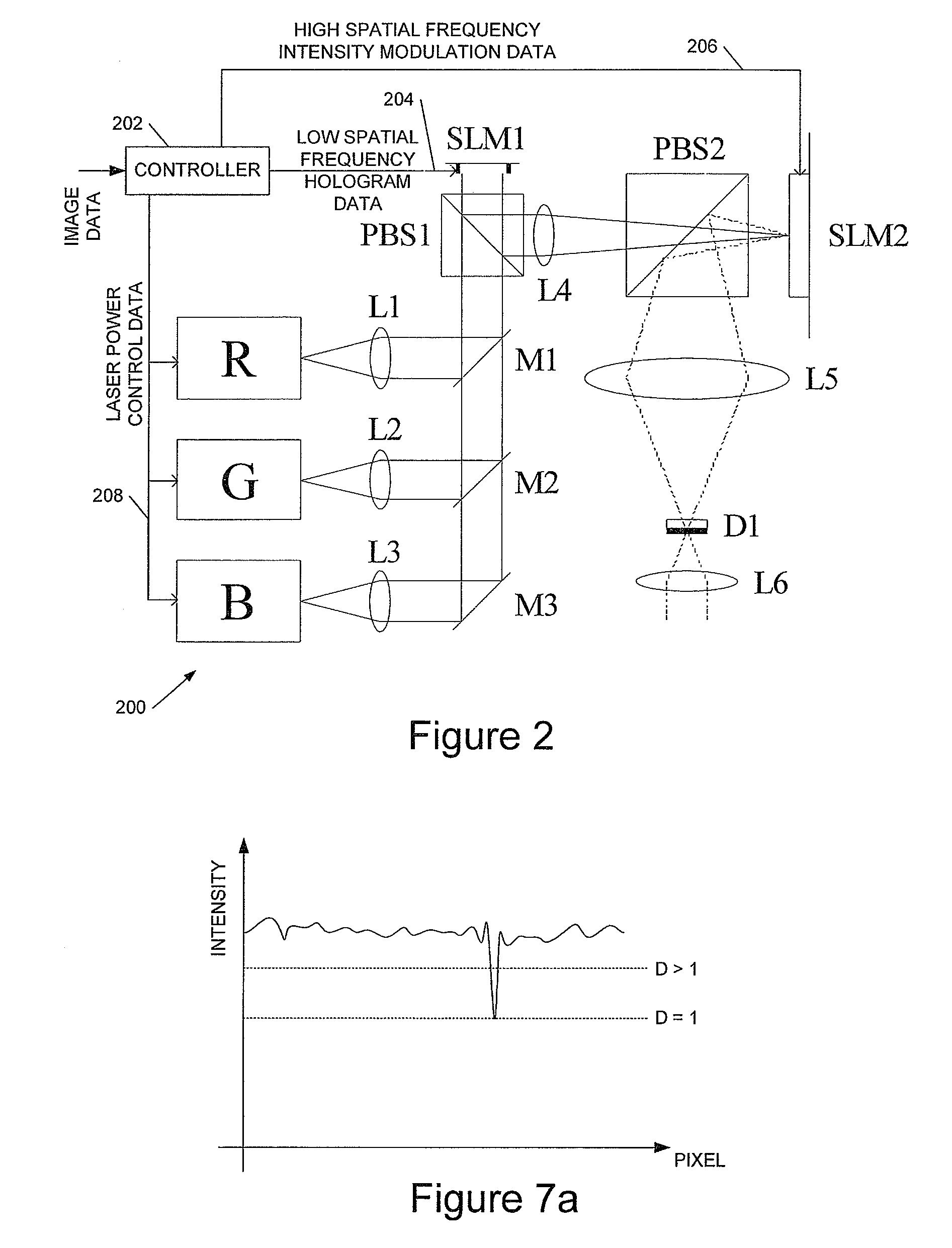
[0034]In preferred embodiments the system includes combining optics to combine red, green and blue laser light from time-multiplexed light sources in order to provide a full colour display. The system may be combined with a controller to provide a holographic image projector as described above. In embodiments the controller provides the functions described above, and is further configured to control the optical power from the one or more laser light sources, in particular dependent upon the calculated intermediate real image from the hologram SLM and upon any scaling applied to increase the optical (diffraction) efficiency of the system.

Problems solved by technology

However the techniques we have previously described are relatively computationally expensive when displaying high-resolution images and, in a hardware (ASIC) implementation the resolution is closely tied to the hardware configuration.
Depending upon the implementation of the technique, more SLM (Spatial Light Modulator) pixels may be employed than are seen as image pixels, which can increase cost and make miniaturisation difficult.
A high contrast image display can also be difficult to achieve.

Method used


Image

  • Holographic image display system
  • Holographic image display system
  • Holographic image display system

Examples


example procedure

[0156

[0157]We now describe an example procedure to implement embodiments of the invention. This example procedure is based on super-resolution ADOSPR but approaches based, for example, on ADOSPR and on sub-segment ADOSPR may also be employed. In general the techniques are not limited to use with an OSPR-type hologram generation procedure, although this is computationally efficient. The procedure assumes a fast phase-modulating (binary or multi-phase) hologram SLM, and a (slower) nematic imaging SLM, although the skilled person will appreciate that other imaging technologies may be equally appropriate.

[0158]In all cases the illumination incident on the SLM is assumed to be Gaussian, with the 1 / e2 intensity at the edges of the SLM.

[0159]Variables[0160]1. The hologram SLM size is M×M pixels.[0161]2. The input image target amplitude, T, is of size P×P pixels. Amplitude range for the input is between 0 (black) and 1 (white).[0162]3. N ADOSPR subframes are to be generated.[0163]4. D is a ...


PUM


Abstract

This invention relates to holographic image display systems, and to related methods and processor control code. We describe a method of displaying an image holographically, the method including: inputting display image data defining said image for display; processing said image data to determine first image data representing a first spatial frequency portion of said image data and second image data representing a second spatial frequency portion of said image data, wherein said second spatial frequency is higher than said first spatial frequency; displaying a hologram of said first image data on a spatial light modulator (SLM) to form a holographically-generated intermediate real image; modulating said intermediate real image using said second image data to display said image.

Description

CLAIM OF PRIORITY[0001]This application claims priority under 35 U.S.C. §119 to United Kingdom Application No. 0813009.8, filed Jul. 16, 2008, which is incorporated in its entirety by reference herein.BACKGROUND OF THE INVENTION[0002]1. Field of the Invention[0003]This invention relates to holographic image display systems, and to related methods and processor control code.[0004]2. Description of the Related Art[0005]We have previously described techniques for displaying an image holographically—see, for example, WO 2005 / 059660 (Noise Suppression Using One Step Phase Retrieval), WO 2006 / 134398 (Hardware for OSPR), WO 2007 / 031797 (Adaptive Noise Cancellation Techniques), WO 2007 / 110668 (Lens Encoding), and WO 2007 / 141567 (Colour Image Display). These are all hereby incorporated by reference in their entirety.[0006]Advantages of holographic image display techniques include a compact optical system and increased optical efficiency as compared with conventional display systems. However ...

Claims


Application Information

Patent Timeline
Patent Type & Authority Patents(United States)
IPC IPC(8): G03H1/08G03H1/04
CPCG03H1/2205G03H1/08G03H2001/221G03H2001/2218G03H2001/2271G03H2001/2284G03H2210/11G03H2210/20G03H2210/40G03H2222/18G03H2222/35G03H2223/12G03H2223/54G03H2225/31G03H2225/32G03H2225/55G03H2225/60G03H2240/56G03H2240/61G03H2210/441G03H1/00G03H1/22H04N5/7416
Inventor CABLE, ADRIAN
Owner DUALITAS LTD
Why Eureka
Eureka Blog
Learn More