Eureka AIR delivers breakthrough ideas for toughest innovation challenges, trusted by R&D personnel around the world.

System for high dynamic range analysis in flow cytometry

a flow cytometry and dynamic range technology, applied in the field of high dynamic range analysis in flow cytometry, can solve the problems of large magnitude of signals produced, many problems, and the inability of analog logarithmic amplifiers to achieve perfect transfer functions, and achieve high resolution requirements, accurate and precise measurement or characterizing the properties of input signals, and the effect of preventing the accumulation of slowly accumulating errors

Active Publication Date: 2007-05-31
BECKMAN COULTER INC
View PDF4 Cites 34 Cited by
  • Summary
  • Abstract
  • Description
  • Claims
  • Application Information

AI Technical Summary

Benefits of technology

[0015] The present invention provides a novel system and method for accurately and precisely measuring or characterizing properties of the input signal, especially for a flow cytometer. Signal parameters may be measured or calculated without many of the limitations or errors previously imposed, perhaps providing more accurate data. The invention may alleviate or avoid issues such as, but not limited to, standard BLR error, analog PSH errors, converter or system non-linearities, multi-region “elbow” effects, and high resolution requirements.
[0016] These ill effects may be avoided or alleviated with all or portions of the present invention. The invention may prevent standard BLR errors, if needed, by not allowing the BLR to adjust during periods of sample acquisition. The base line may be removed before acquisition or between events and held constant during pulses. If necessary, during high event rates, the base line may be held constant to prevent error from slowly accumulating. If no error is allowed to enter into the system from the BLR circuit, the eventual results may be more accurate and precise.
[0017] In some embodiments the present invention may remove converter or system nonlinearities, if needed, by determining the errors and then compensating for them. For example, an analog logarithmic amplifier may be used as a signal converter, but it may contain non-linearities. However, in some embodiments, the invention can provide a means of determining the errors in the transfer function, and a means of applying a correction scheme to reduce or eliminate the error. By removing the non-linearities of the system, result accuracy and precision may again be improved.
[0018] In other embodiments, the present invention may separate the required digitization resolution from the sampled dynamic range This may provide a tremendous benefit by allowing an analysis of a much larger dynamic range, and by allowing for flexibility in analyzing different dynamic ranges. Embodiments may accomplish this by applying a non-linear transfer function to the input signal, which may effectively compress a very large dynamic range into a much smaller one by applying greater gains at lower magnitudes. The non-linear transfer function may even be matched to the desired dynamic range and desired response, producing a new signal that may be analyzed at a lower resolution while still providing adequate resolution for the low end of the dynamic range.
[0019] In particular, the present invention utilizes an enhanced BLR that may be locked during acquisition to remove any DC offset of an input signal. The baseline corrected signal may then be transformed by a logarithmic amplifier that is, perhaps, calibrated with gain and offset adjustments, and may then be sampled by an ADC and input to a processor. The processor may accept one or more channels of data, with one or more processors per board, and one or more boards per system. This may allow for a flexibility of overall number of channels. The processor may be used to perform the digital PSH function, as well as to calculate or generate any other parameters desired, or provide other needed functionality.
[0020] Therefore, by, in part or in combination, eliminating standard BLR errors, removing system or converter non-linearities, and separating digitization resolution from dynamic range, embodiments of the present invention may provide more accurate and precise results for high dynamic ranges and high event rates than previously possible, especially as applied to a flow cytometer.

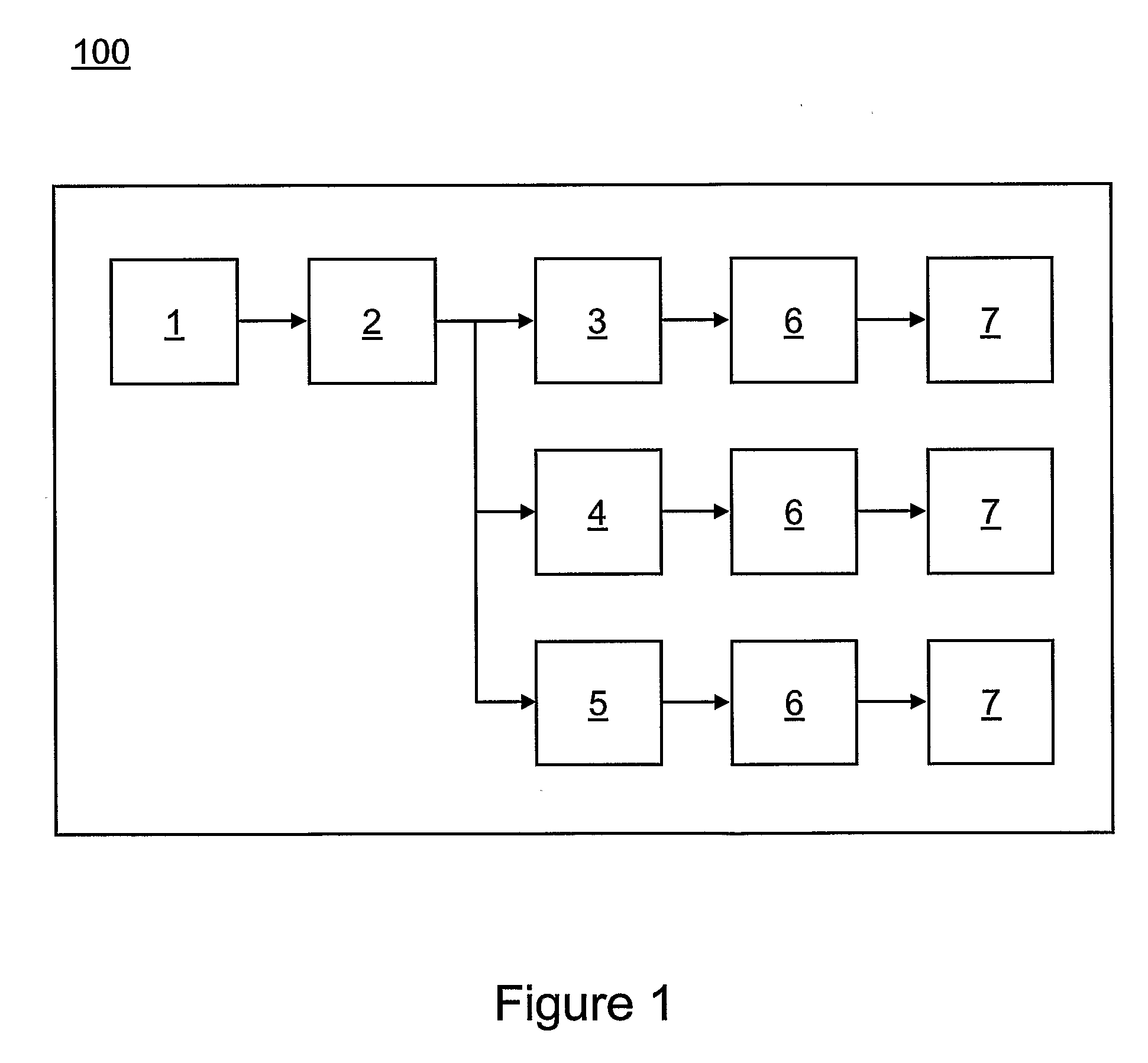
Problems solved by technology

However, depending on particle size, the particular chemicals used, laser power, and many other factors, the signals produced may occupy a large range of magnitudes.
Furthermore, some systems require analyzing particles at rates of over 50,000 per second, but also possibly as slow as only several per second.
Accurate analysis over this large range of magnitudes and event rates has introduced many problems.
These types of systems give a good starting point for signal analysis, but have some inherent problems.
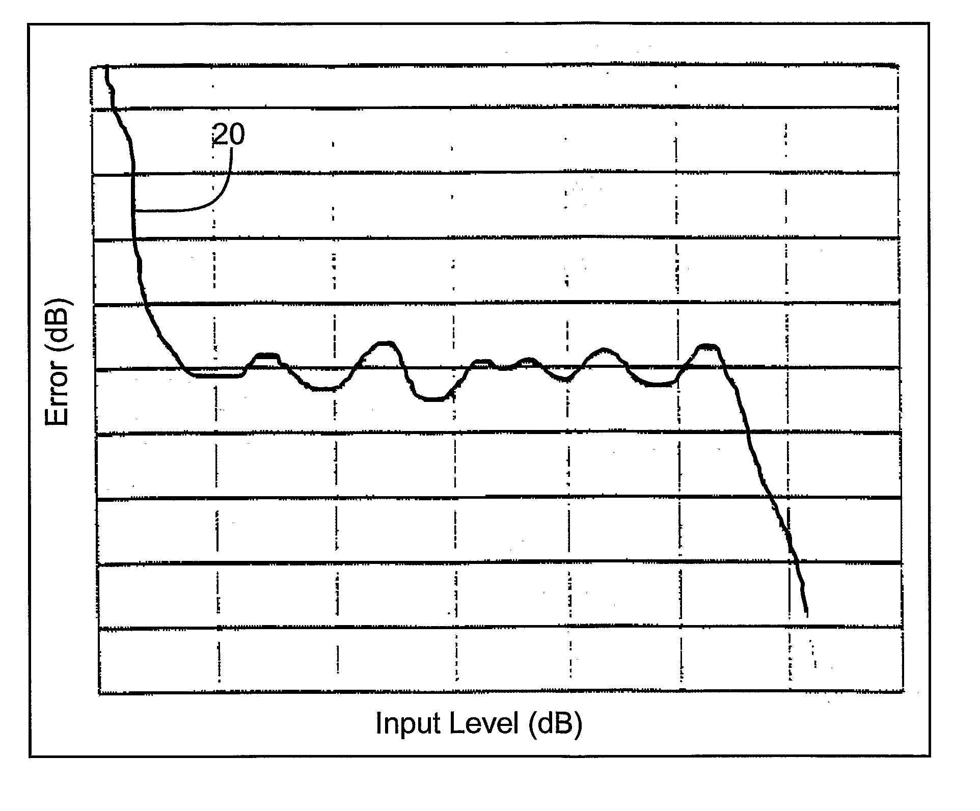
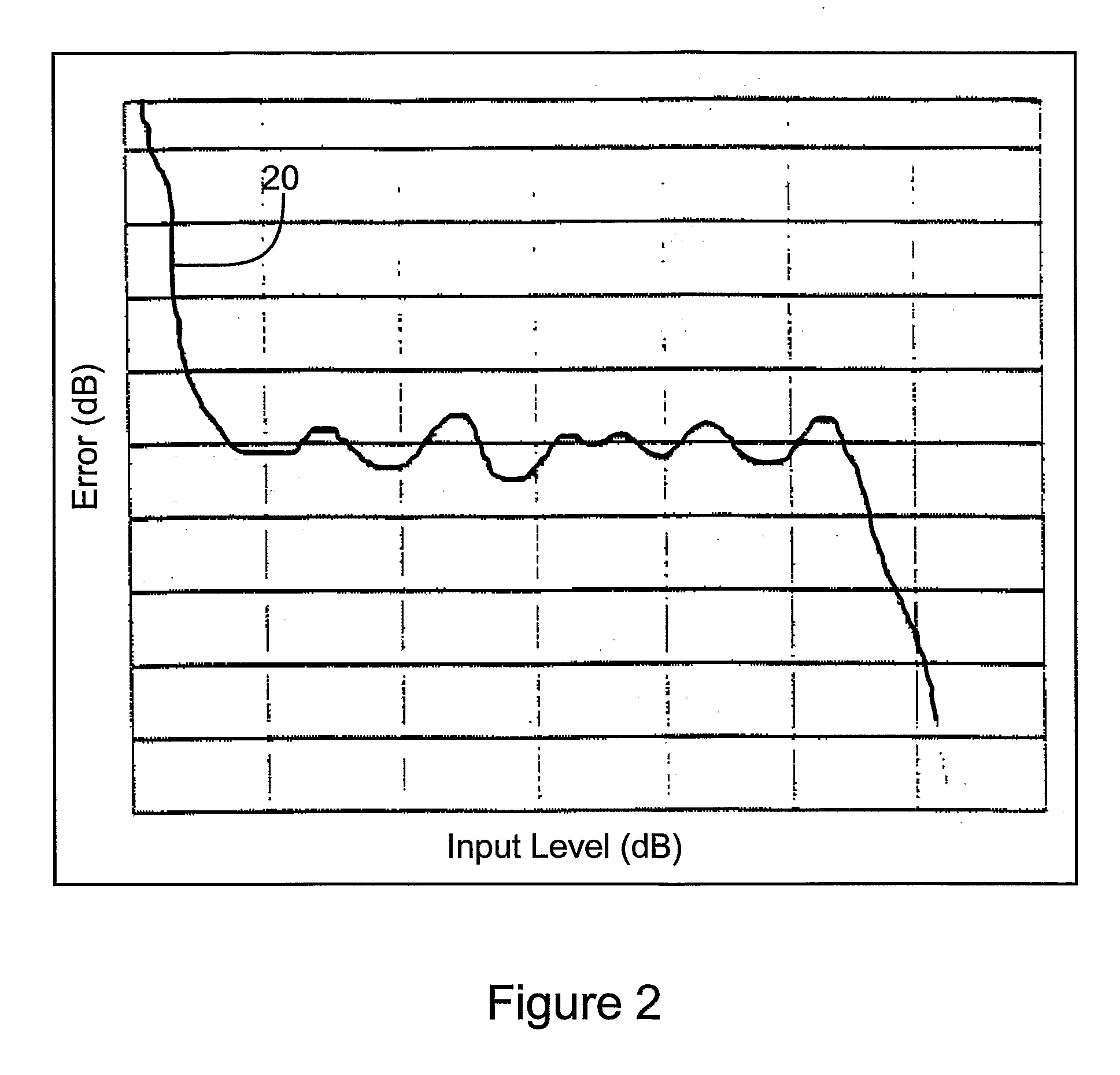
Analog logarithmic amplifiers usually do not have a perfect transfer function and can contain “ripples” that may distort the input signal.
Thus, the output can be higher or lower than it should have been depending upon the input magnitude, which introduced errors into calculations and distorted population histograms.
Analog PSH circuits can have several problems, such as noise susceptibility, that may add to the inherent error of the system.
In some case, especially at very high event rates, the standard BLR circuit may introduce errors of its own.
This error, which may manifest itself as a DC bias, may cause pulse distortion as the logarithmic amplifier input crosses from positive to negative and back to positive.
However, these systems did not always eliminate all of the problems, and sometimes introduced some of their own.
Some of the problems with this system include: 1.
Transitions from one gain stage to another may not be necessarily perfect, and may create “elbow” effects of non-linear regions.
However, this type of system also may have introduced some problems.
The problems with this type of system include analysis dynamic range is sometimes limited to ADC resolution perhaps because the signal is directly sampled.
This may mean that system dynamic range may be limited by ADC technology.
To achieve the necessary high resolution, sample speed may need to be given up, which may limit the speed that the signal may be sampled at, which may further limit the speed of overall analysis.
Prior work for particle analysis electronics in flow cytometry has apparently failed to solve these challenges without introducing new problems.

Method used


Image

  • System for high dynamic range analysis in flow cytometry
  • System for high dynamic range analysis in flow cytometry
  • System for high dynamic range analysis in flow cytometry

Examples


Embodiment Construction

[0029] The present invention includes a variety of aspects, which may be combined in different ways. The following descriptions are provided to list elements and describe some of the preferred embodiments of the present invention. These elements are listed with initial embodiments. However, it should be understood that they may be combined in any manner and in any number to create additional embodiments. The variously described examples and preferred embodiments should not be construed to limit the present invention to only the explicitly described systems, techniques, and applications. Further, this description should further be understood to support and encompass descriptions and claims of all the various embodiments, systems, techniques, methods, devices, and applications with any number of the disclosed elements, with each element alone, and also with any and all various permutations and combinations of all elements in this or any subsequent application.

[0030] As mentioned abov...


PUM

PropertyMeasurementUnit
optical measurementsaaaaaaaaaa
DC voltageaaaaaaaaaa
wavelengthsaaaaaaaaaa

Abstract

A flow cytometer (700) capable of using electronics (7, 9) to analyze a large dynamic range while avoiding and / or correcting traditional limitations of acquisition electronics. The invention allows for measuring signal characteristics, which may include but are not limited to linear peak, integral, logarithmic peak, and pulse width. Other system parameters may also be generated by the invention to indicate timing or status information. Accurate and precise measurements may be performed by correcting for input errors if needed, and by transforming the input signal (1) to produce a more easily measured form.

Description

TECHNICAL FIELD [0001] This invention relates to a method and apparatus for the analysis, and possible sorting, of particles, e.g. in a flow cytometer. BACKGROUND ART [0002] Flow cytometers typically analyze particles by applying a stain or reagent, suspending them within a stream of sheath fluid, and passing the stream linearly through a laser. When the laser strikes the particles, it produces several channels of information in the form of scattered light and emitted light at different wavelengths. Traditionally photo diodes and / or photo multiplier tubes are then used to convert the optical signal into an electronic signal, which may then be measured and characterized. However, depending on particle size, the particular chemicals used, laser power, and many other factors, the signals produced may occupy a large range of magnitudes. A small, unstained particle or “negative” particle may produce a signal with magnitude of only 1 / 1000th or less than that of a large, stained particle. ...

Claims


Application Information

Patent Timeline
Patent Type & Authority Applications(United States)
IPC IPC(8): G06F19/00G01N15/14
CPCG01N15/1429G01N2015/149G01N15/1459G01N15/149
Inventor JOCHUM, THEODORE W.FOX, DANIEL N.THRASHER, THOMAS L.MALACHOWSKI, GEORGE
Owner BECKMAN COULTER INC
Why Eureka
Eureka Blog
Learn More