Multispectral lighting apparatus

Active Publication Date: 2010-01-21
CARL ZEISS MICROSCOPY GMBH
View PDF8 Cites 16 Cited by
  • Summary
  • Abstract
  • Description
  • Claims
  • Application Information

AI Technical Summary

Benefits of technology

[0041]The illumination devices described above are suitable for fluorescent illumination of samples. In fluorescence microscopy, a distinction is made with respect to incident fluorescence in which the excitation light impinges on the sample from the same side from which the sample is observed. In transmitted-light fluorescence which is used in more expensive microscope systems, the sample is irradiated by transmitted light with illumination and observation taking place from opposite sides. A drawback of transmitted-light fluorescence consists in that the excitation radiation impinges on the emission filter at full intensity and, further, the excitation of the sample is dispersed to varying degrees, weaker and stronger, in thick samples. However, LEDs in particular are especially suited to transmitted-light fluorescence because their spectrum is narrow compa

Problems solved by technology

However, since LEDs have narrow emission spectra, an arrangement of this kind covers only part of the spectrum for fluorescence experiments.
Obviously, an illumination device comprising this many LEDs would be complicated and expensive to build.
Further, the space requirement for this is large and space would be taken up in the laboratory.
An expansion of this

Method used


Image

  • Multispectral lighting apparatus
  • Multispectral lighting apparatus
  • Multispectral lighting apparatus

Examples


Embodiment Construction

[0050]It is to be understood that the figures and descriptions of the present invention have been simplified to illustrate elements that are relevant for a clear understanding of the present invention, while eliminating, for purposes of clarity, many other elements which are conventional in this art. Those of ordinary skill in the art will recognize that other elements are desirable for implementing the present invention. However, because such elements are well known in the art, and because they do not facilitate a better understanding of the present invention, a discussion of such elements is not provided herein.

[0051]The present invention will now be described in detail on the basis of exemplary embodiments.

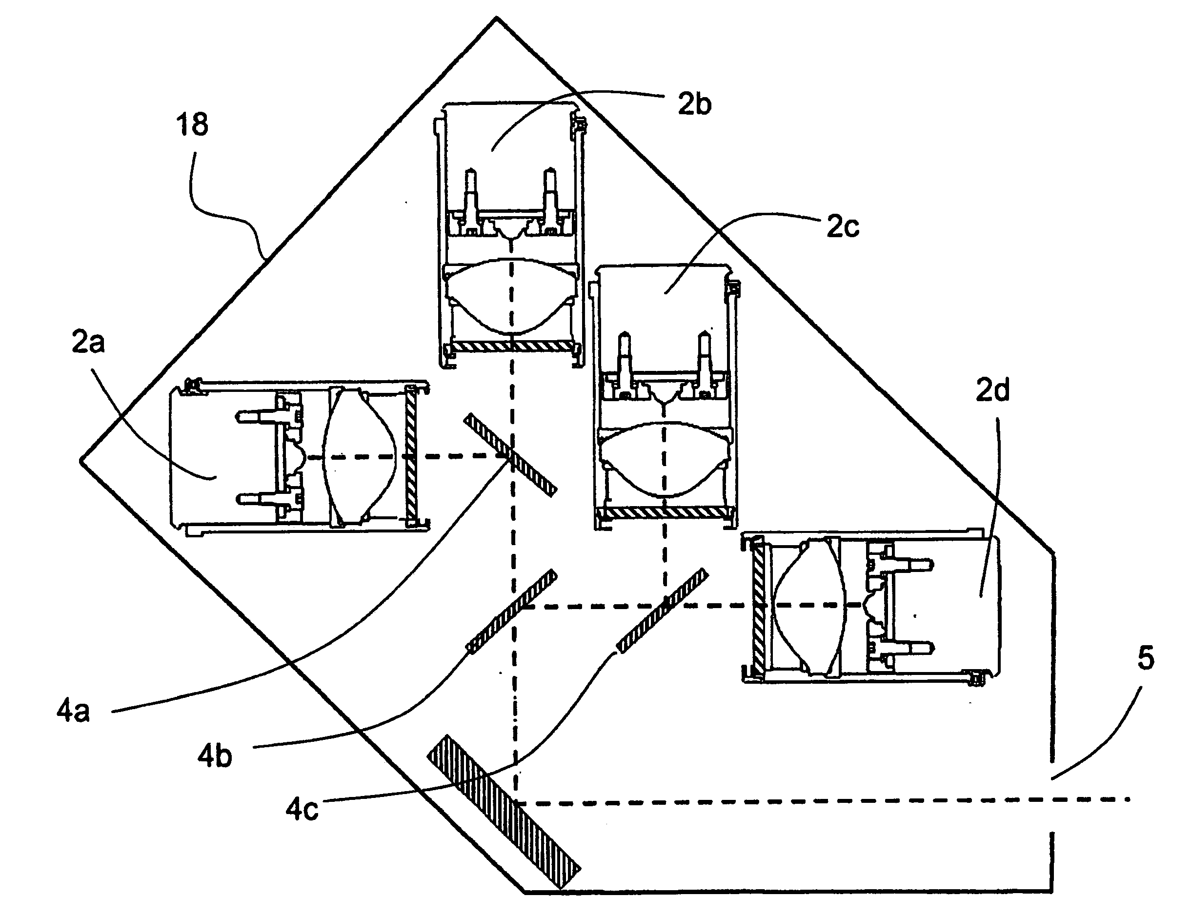
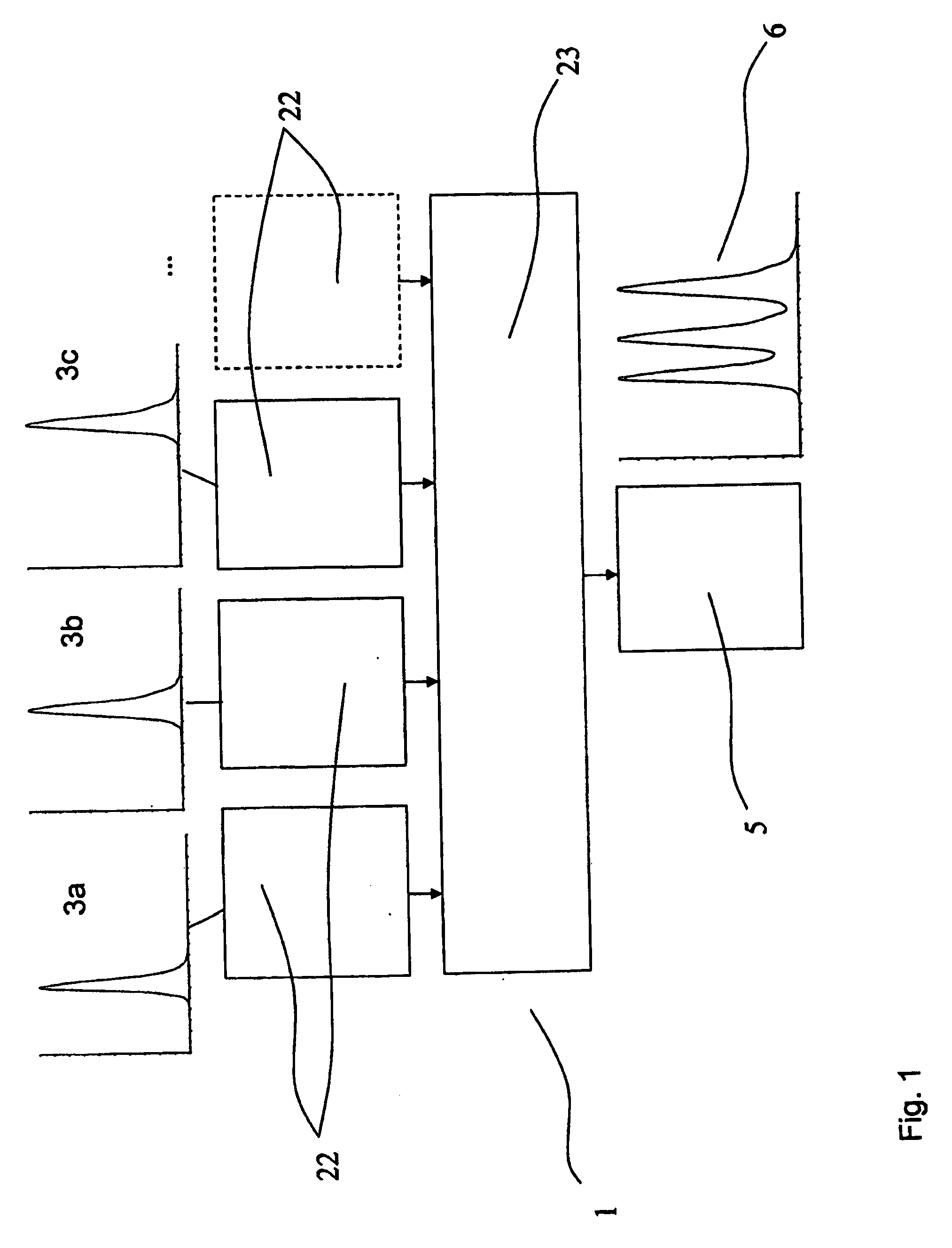
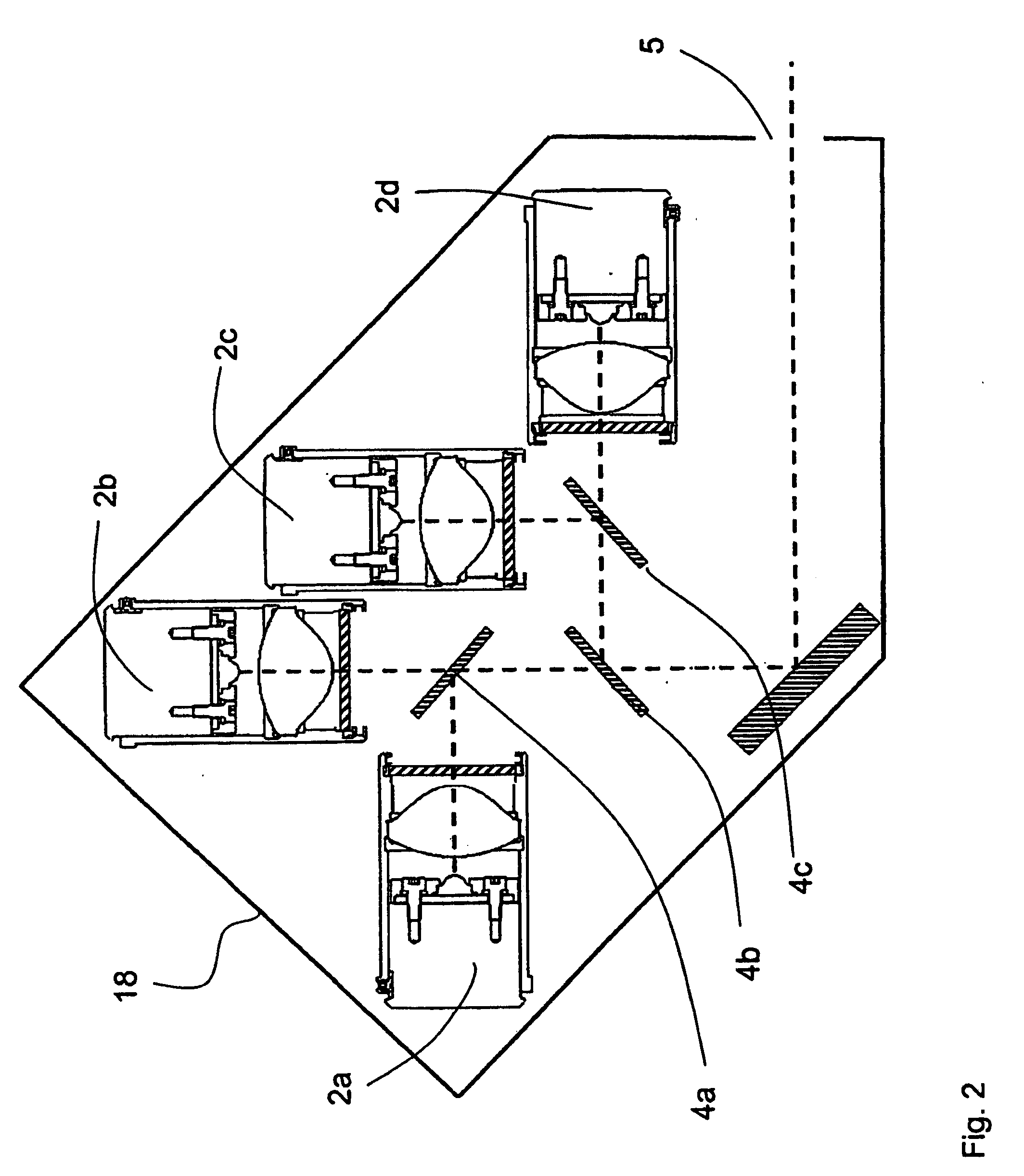
[0052]The multispectral illumination device 1 according to the invention is shown schematically in FIG. 1. The at least three receptacle positions for lighting modules 22 and at least one receptacle position for coupling modules 23 make it possible to couple different individua...


PUM


Abstract

The invention is directed to a multispectral illumination device for a microscope or for a reader. According to the invention, the illumination device comprises at least three receptacle positions for lighting modules and at least one receptacle position for coupling modules, the mechanical devices for connecting the lighting modules or coupling modules at the receptacle positions to the illumination device being designed in such a way that the lighting modules or coupling modules can be easily changed. Further, the receptacle positions are arranged in such a way that, with suitable selection of the lighting modules and coupling modules, all individual spectra of the lighting modules in a total spectrum are available simultaneously at the output of the illumination device.

Description

[0001]The present application claims priority from PCT Patent Application No. PCT / EP2007 / 008693 filed on Oct. 6, 2007, which claims priority from German Patent Application No. DE 10 2006 048 05 54.6 filed on Oct. 11, 2006, the disclosure of which is incorporated herein by reference in its entirety.BACKGROUND OF THE INVENTION[0002]1. Field of the Invention[0003]The invention is directed to a multispectral illumination device for a microscope or for a reader.[0004]2. Description of Related Art[0005]An important application for illumination devices is in arrangements for imaging and examination which are provided for generating images of an object or sample to be examined. Typical examples of such imaging devices are microscopes, particularly microscopes with widefield optics which image a given area of the sample to be imaged or examined. Fluorescence examination plays a special role in the optical examination of samples. In this case, the sample is irradiated by an excitation beam wi...

Claims


Application Information

Patent Timeline
IPC IPC(8): G02B21/06
CPCG01J3/02G01J3/0208G01J3/10G02B27/145G02B21/16G02B27/1006G01N21/6458
Inventor NOLTE, ANDRESSKRAMER, MATTHIASBREHM, MICHAELBOEKER, CHRISTIAN
Owner CARL ZEISS MICROSCOPY GMBH
Why Eureka
Try Eureka