Permittivity Monitor uses Ultra Wide Band Transmission

a technology of transmission and transmitter, applied in the field of electronic moisture sensors, can solve the problems of invalid calibration, unsuitable probing-type measurement, and too dry soil, and achieve the effects of narrowing the spectrum, simplifying requirements, and fast rise and fall times

Inactive Publication Date: 2005-04-28
TECHN DEV CONSULTANTS
View PDF7 Cites 5 Cited by
  • Summary
  • Abstract
  • Description
  • Claims
  • Application Information

AI Technical Summary

Benefits of technology

[0011] A very narrow pulse with fast rise and fall times has a broad spectral content with uniform amplitude, sin(x) / x distribution, across its spectrum. When transmitted from a broadband antenna, such a pulse propagates as an electromagnetic wave through any medium that is either non-conductive or of low conductivity. The antennas act as high-pass filters, removing the lower frequency and direct current components, resulting in a doublet waveform from the receiving antenna. This simplifies the requirements of the broadband transmitting and receiving antennas and also narrows the spectrum for preservation of group delay. The low-side truncated spectrum facilitates efficient wireless propagation while preserving high frequency characteristics from which propagation time and rise time degradation can be measured.

Problems solved by technology

One cause of crop stress is allowing the soil to become too dry.
They are not well suited for probing-type measurements because they cannot be installed in the soil without excavation.
This hindrance arises from the fact that the transmission line attached to the device is in the form of a loop and is not easily inserted into the soil.
If the soil chemistry changes due to salts or fertilizer content of the soil, then the calibration becomes invalid.
The accuracy of such devices is also inferior to the TDR and TDT devices discussed above.
Current electronic methods used for monitoring soil moisture are subject to errors caused by compaction, electrical conductivity and temperature of the soil.

Method used


Image

  • Permittivity Monitor uses Ultra Wide Band Transmission
  • Permittivity Monitor uses Ultra Wide Band Transmission
  • Permittivity Monitor uses Ultra Wide Band Transmission

Examples


Embodiment Construction

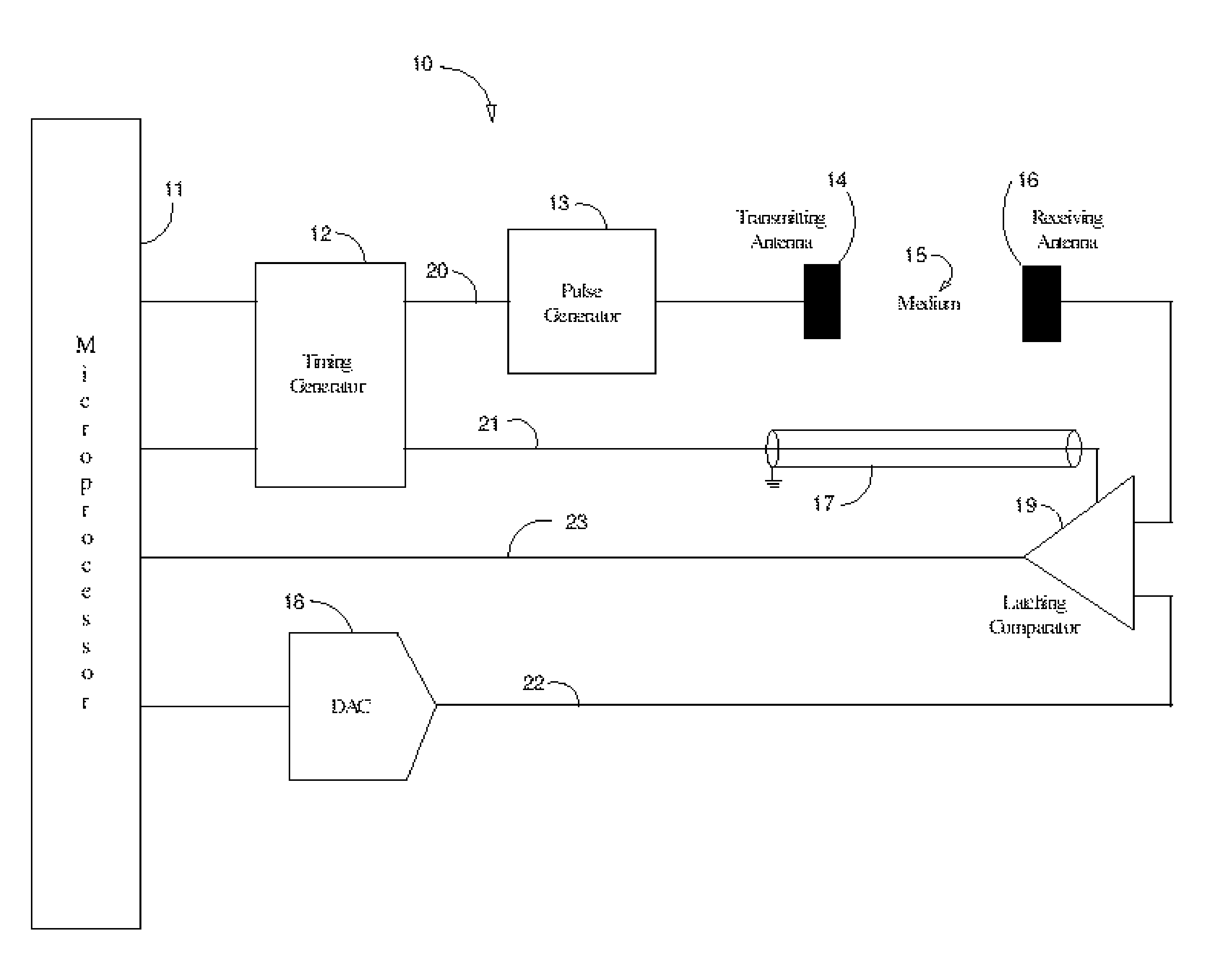
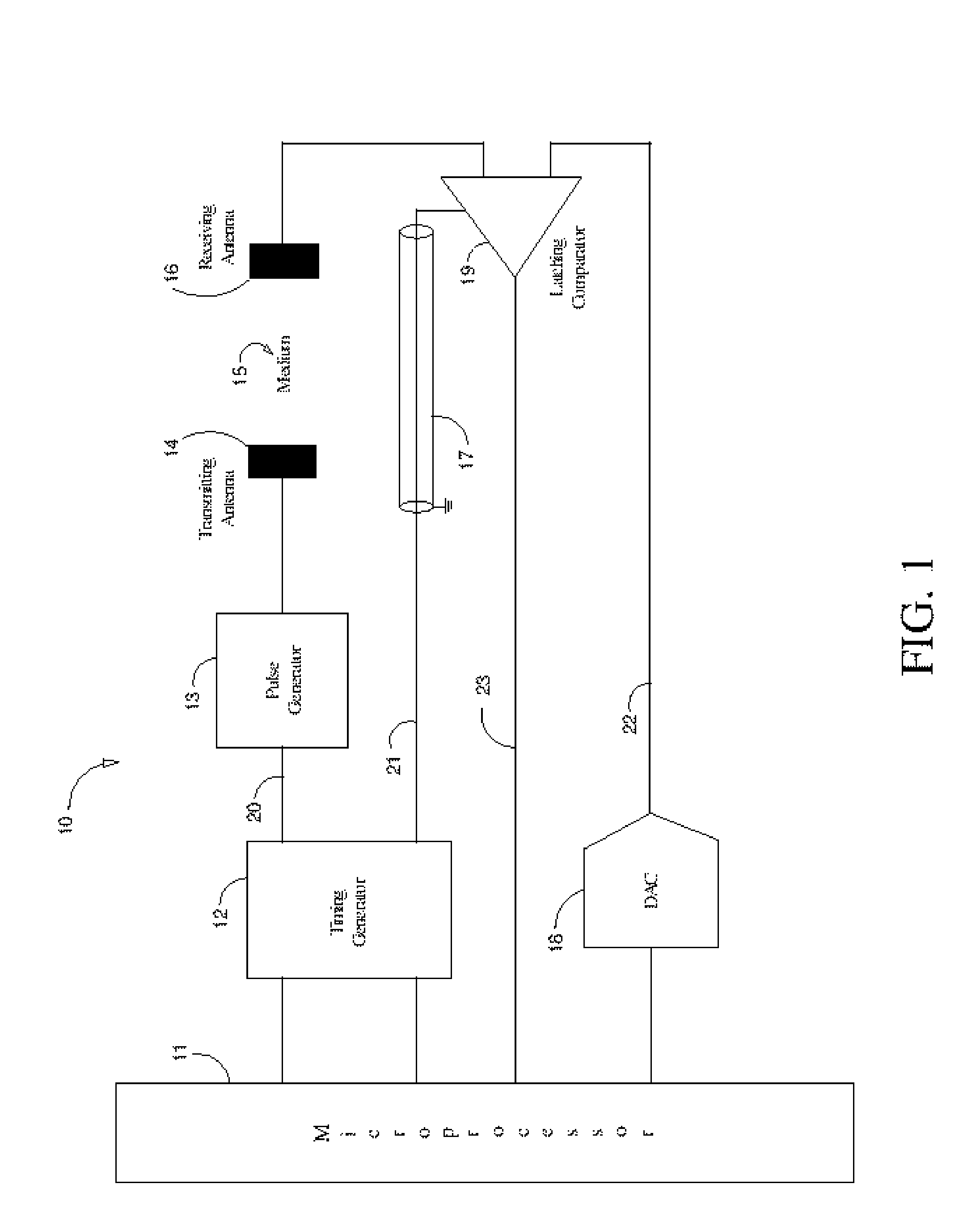
[0016] Use of the Time Domain Reflectometry (TDR) techniques disclosed in U.S. Pat. No. 6,831,468 allow for a physical separation of the transmitting and receiving unit of U.S. Pat. No. 6,657,443. An embodiment of the present invention results when the unshielded transmission line of '468 that would normally be immersed in the medium being measured is replaced by a wireless connection using a transmitter and receiver antenna pair.

[0017]FIG. 1 is a representation of an embodiment of a Permittivity Monitor 10 of the present invention. The pulse transmitter in this system comprises a pulse generator 13 that drives a broadband transmitting antenna 14 with narrow pulses. Each pulse can be generated by first generating a fast transitioning step function using a step recovery diode, an avalanche transistor, a GaAs transistor, a SiGe transistor or other ultra fast device. The step function can then be converted to a narrow pulse using a shorted transmission line stub connected across the s...


PUM

PropertyMeasurementUnit
lengthaaaaaaaaaa
permittivityaaaaaaaaaa
timeaaaaaaaaaa

Abstract

Narrow pulses transmitted wirelessly from a transmitting antenna to a receiving antenna are used to measure the electrical permittivity of the medium of interest between the two antennas. Timing signals are transmitted along a shielded transmission line coincident with the wireless transmission through the medium. The received waveform is digitized in the time domain and analyzed to determine the propagation time. The effects of dispersion caused by the conductive and dielectric properties of the medium on the transmitted waveform are overcome through analysis of the digitized waveform, resulting in an accurate measurement of the propagation time and thus the permittivity of the medium, from which volumetric moisture content may be derived.

Description

CROSS-REFERENCES TO RELATED APPLICATIONS [0001] This application claims benefit of U.S. Provisional Application No. 60 / 534,293, filed Jan. 5, 2004, entitled “Permittivity monitor+, which is incorporated here by reference in its entirety. [0002] This application is a Continuation-In-Part of co-pending U.S. patent application Ser. No. 10 / 367,688, filed Feb. 19, 2003, entitled “Method and Apparatus for Determining Moisture Content and Conductivity,” which is incorporated here by reference. FIELD OF THE INVENTION [0003] The present invention relates generally to electronic moisture sensors. In particular the described invention relates to a means of deriving moisture content of a medium based upon measurement of its permittivity. An ultra wide band transmission is used to measure permittivity with reliance upon certain techniques disclosed in U.S. Pat. No. 6,657,443 as those techniques are applied in a wireless manner to a topology that is related to but distinct from those described in...

Claims


Application Information

Patent Timeline
Patent Type & Authority Applications(United States)
IPC IPC(8): G01N33/24G01R27/04G01R27/32
CPCG01N33/246
Inventor ANDERSON, SCOTT K.
Owner TECHN DEV CONSULTANTS
Why Eureka
Try Eureka