Panel antenna with variable phase shifter

a phase shifter and panel antenna technology, applied in the direction of antennas, antenna details, antenna feed intermediates, etc., can solve the problems of unsatisfactory variations in both reflected and transmitted energy, the wiper may bind or require excessive force to move, and the overall structure is large, complex, and expensiv

Active Publication Date: 2006-04-13
COMMSCOPE TECH LLC
View PDF27 Cites 47 Cited by
  • Summary
  • Abstract
  • Description
  • Claims
  • Application Information

AI Technical Summary

Problems solved by technology

If the spacing between the wiper conductive element and the conductive arc varies significantly as the wiper is pivoted along the conductive arc, the capacitive coupling between the two conductors will vary, causing undesired variations in both reflected and transmitted energy.
On the other hand, if the wiper is pressed too firmly against the trace, the wiper may bind or require excessive force to move.
In the current art these various functions of providing mechanical wiper support and remote position adjustment are accomplished with multiple parts which undesirably increase the size, cost, complexity, and reliability of the overall structure.
This causes several problems.
One is that extending the wiper substrate to

Method used


Image

  • Panel antenna with variable phase shifter
  • Panel antenna with variable phase shifter
  • Panel antenna with variable phase shifter

Examples


Embodiment Construction

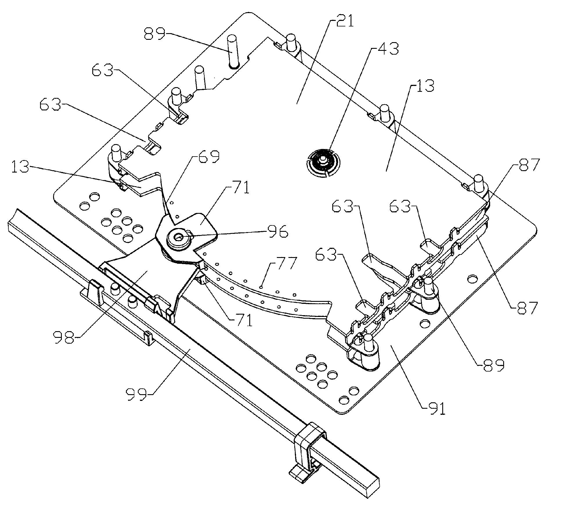
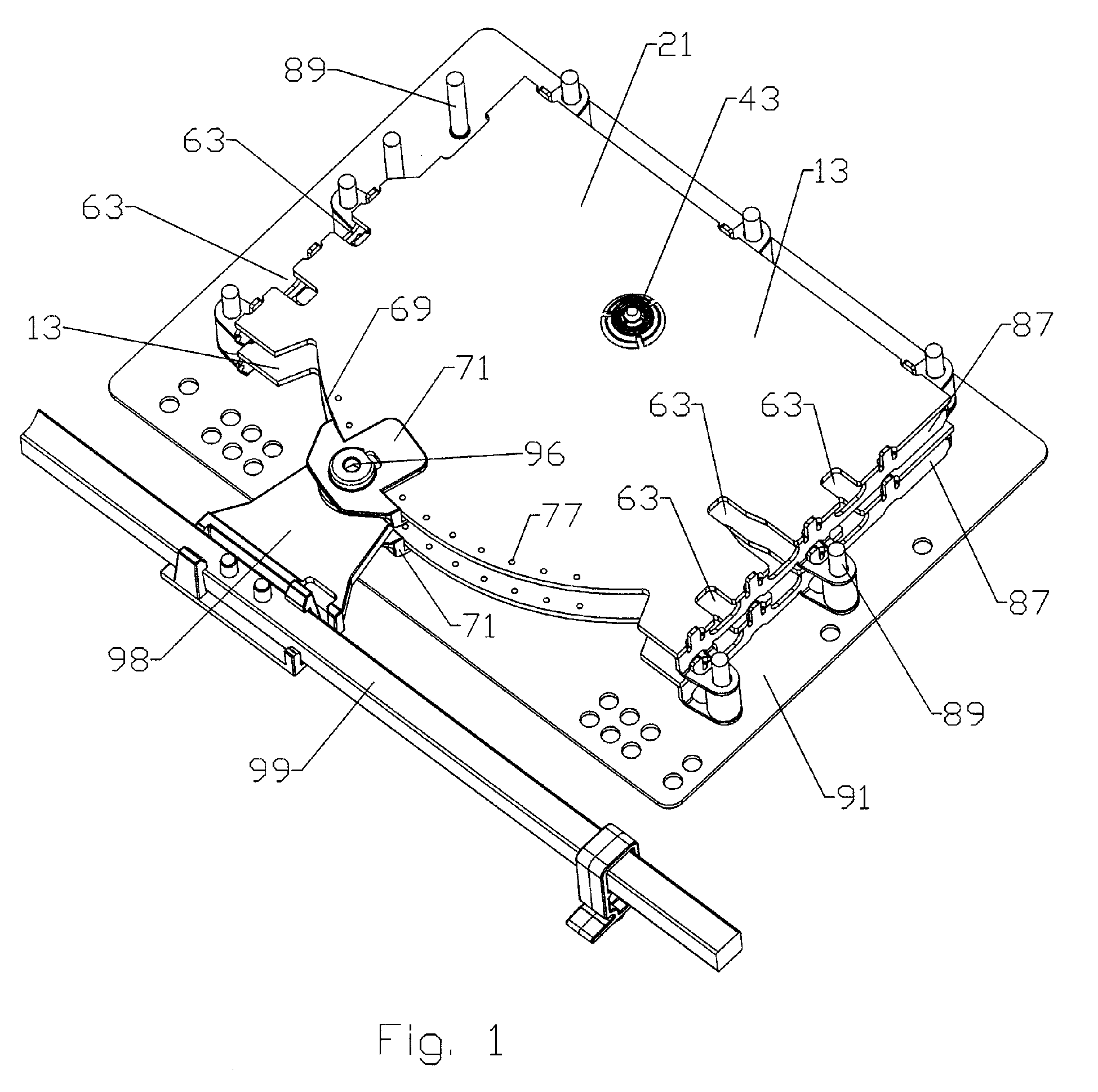
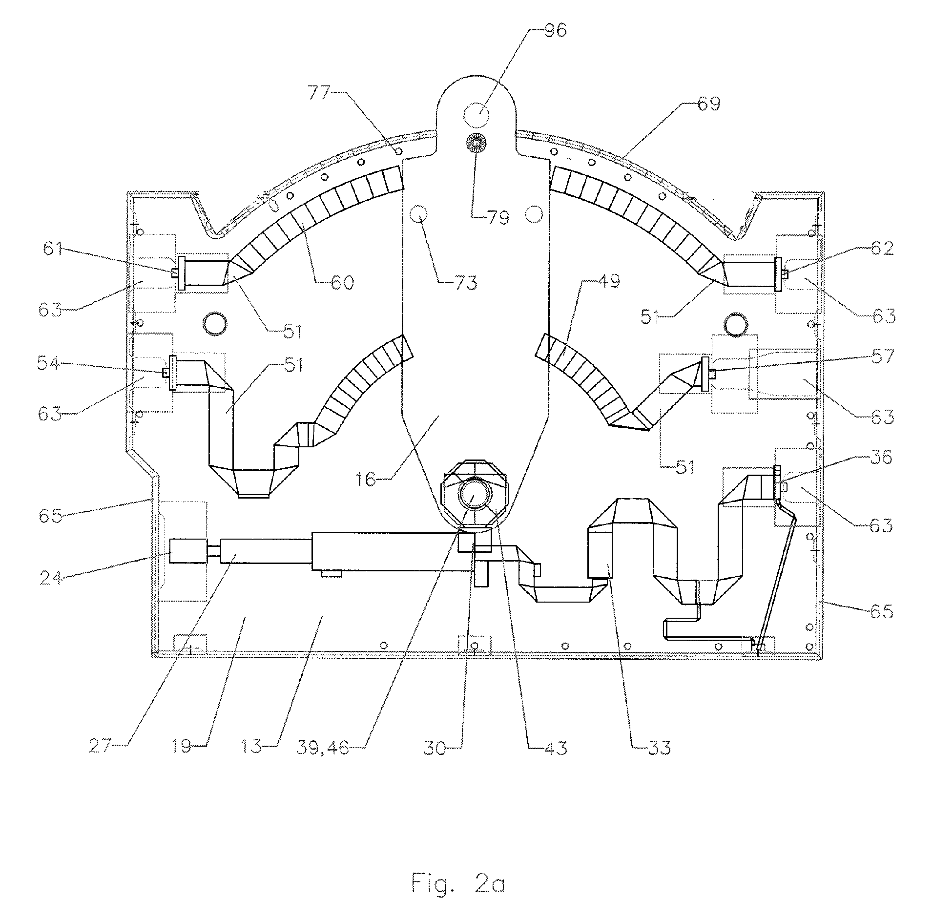
[0033] The present invention addresses and resolves a multitude of the shortcomings of panel antennas for use in cellular communication systems and particularly those employing differential-type capacitive wiper phase shifter technology. As will be explained at length below, by making a number of changes in prior art approaches, radical improvements in cost and compactness of the phase shifter system and in the embodying panel antenna are achieved.

[0034] Among the structural improvements leading to a variety of benefits and features is the use of a low cost dielectric substrate for the wiper and the use of conductive trace on the side of the wiper substrate facing the conductive arc and backplane. By this simple but completely previously overlooked inversion of the wiper substrate, the wiper body no longer must be composed of microwave quality material which is extremely expensive and structurally very weak. Rather, the wiper body according to the invention is preferably composed o...


PUM


Abstract

A panel antenna having a variable phase shifter module with at least one main-PCB having an input trace coupled to a wiper junction. An arcuate trace on the main-PCB extending between a first output trace and a second output trace, the arcuate trace having an arc center proximate the wiper junction. A wiper-PCB having a linking trace thereon; the wiper-PCB rotatably coupled to the main-PCB proximate the wiper junction with the linking trace facing the first main-PCB. Because the linking trace faces the main-PCB, the wiper-PCB may be formed from inexpensive and structurally resilient substrate material. The linking trace coupling the wiper junction with the arcuate trace. Multiple arcuate traces may be linked to further output traces to add additional outputs, each having variable phase shift between them, depending upon the position of the wiper-PCB. Multiple main-PCBs may be stacked upon each other and the wiper-PCBs of each controlled by a common linkage.

Description

BACKGROUND [0001] 1. Field of the Invention [0002] This invention relates to a cellular base station communication system and more particularly to a panel antenna having a compact stackable variable phase shifter. [0003] 2. Description of Related Art [0004] Differential variable phase shifters introduce a desired phase shift between RF energy split between two or more outputs. Differential variable phase shifters are useful, for example, as components in the electrically variable beam elevation and or azimuth scan angle antenna systems of cellular communications base stations. The desired phase shift is typically obtained by modifying the electrical path required to reach each output with respect to the other output(s). To adjust the electrical path in one common design approach, a transmission line conductive arc has an associated wiper, pivoted at the center of the arc, which is moved along the surface of the arc, apportioning the length of an electrical path from the wiper input ...

Claims


Application Information

Patent Timeline
IPC IPC(8): H01Q3/22
CPCH01Q3/32H01Q1/246H01Q3/005
Inventor ZIMMERMAN, MARTIN
Owner COMMSCOPE TECH LLC
Why Eureka
Try Eureka