
Remote communication device and system for communication

a communication device and a technology for remote communication, applied in the direction of electrical controllers, program control, instruments, etc., to achieve the effect of increasing processing gain, effective use of oversampling, and potent lack of interferen

Active Publication Date: 2004-12-09
STEMCO PROD INC
View PDF11 Cites 42 Cited by
  • Summary
  • Abstract
  • Description
  • Claims
  • Application Information

AI Technical Summary

Benefits of technology

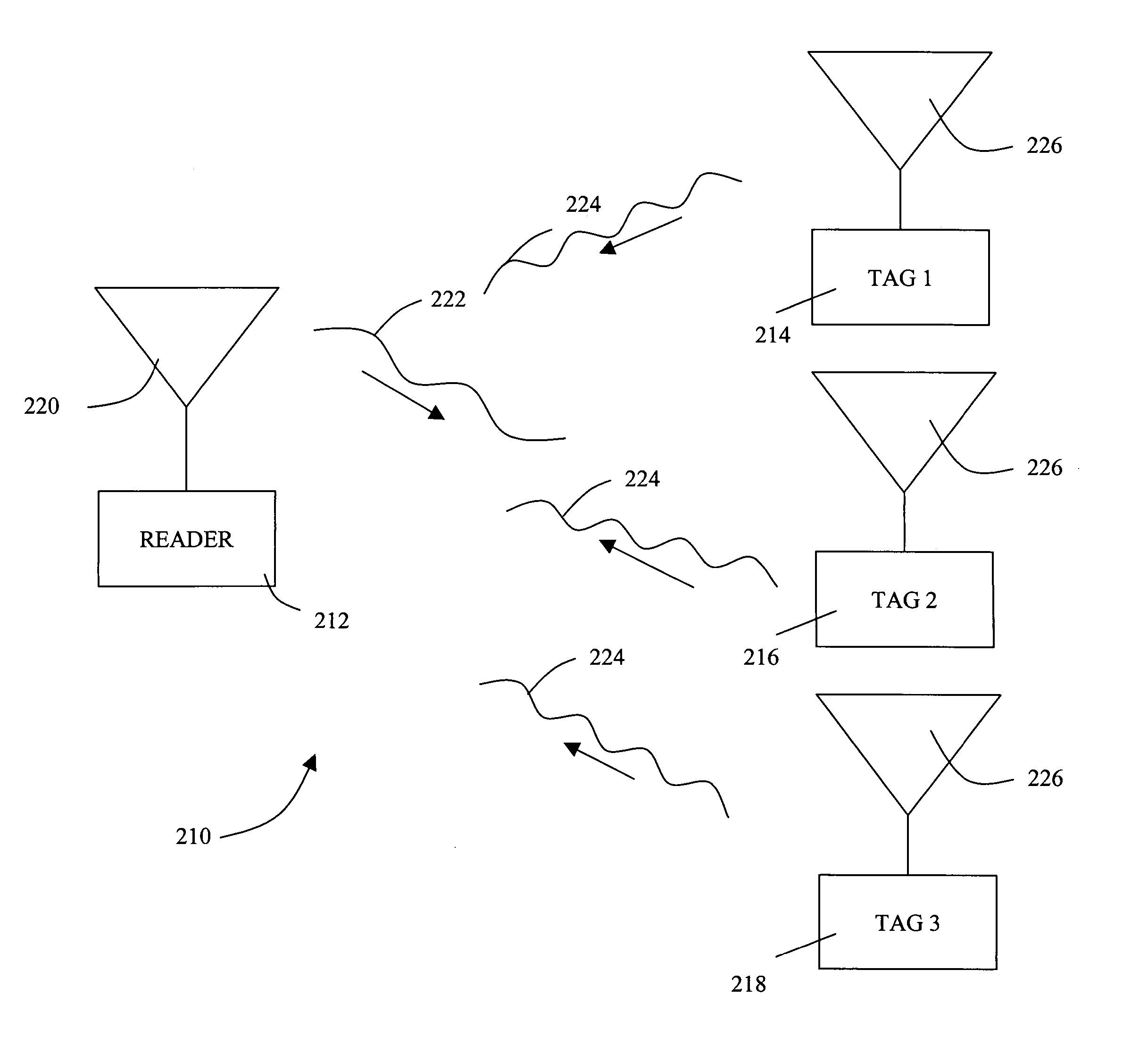
[0015] A potential advantage of the present invention is that the remote communication device may not be required to turn its carrier on and off in a biphase modulation technique to avoid interference with other remote communication devices. Rather, the remote communication device may use a frequency-hopping carrier to communicate back to the reader.
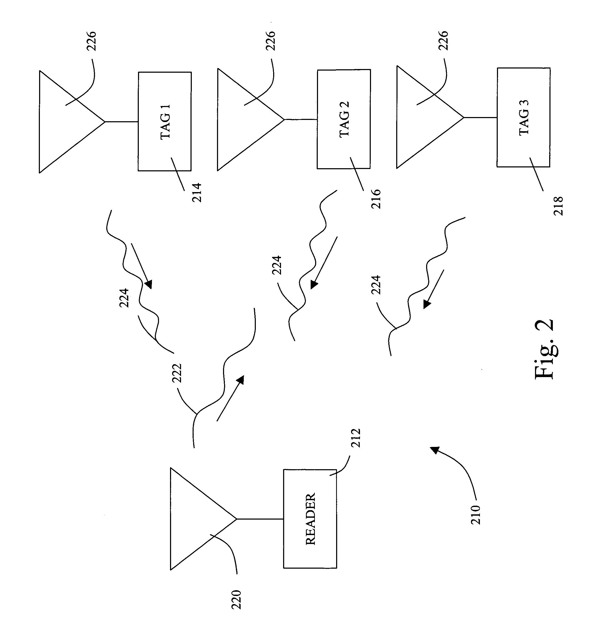
[0016] Another potential advantage of the present invention is the potential lack of interference between multiple devices in a RF system since each remote communication device in a system may be assigned a separate identification bandwidth.
[0017] Another potential advantage to the system of the present invention is that the system may allow the reader to effectively use oversampling, decimation, and averaging to increase the processing gain with no loss in data detection. Low signal to noise levels can be processed once the initial lock on a remote communication device's signal is made because the reader can then predict the range of possible frequencies (encoding frequencies) of the signal. The reader may then zoom in for a very narrowband view of the identification bandwidth and the encoding frequencies contained therein.
[0018] The demodulation technique for one backscattered signal may be used to extract data from the other backscattered signals received by the reader from the remote communication devices and thereby potentially simplifying the system's computing requirements.
[0019] Another advantage of the present system may include an overall increase in the data rate or the corresponding symbol rate may be reduced if data communications rates do not need to increase.
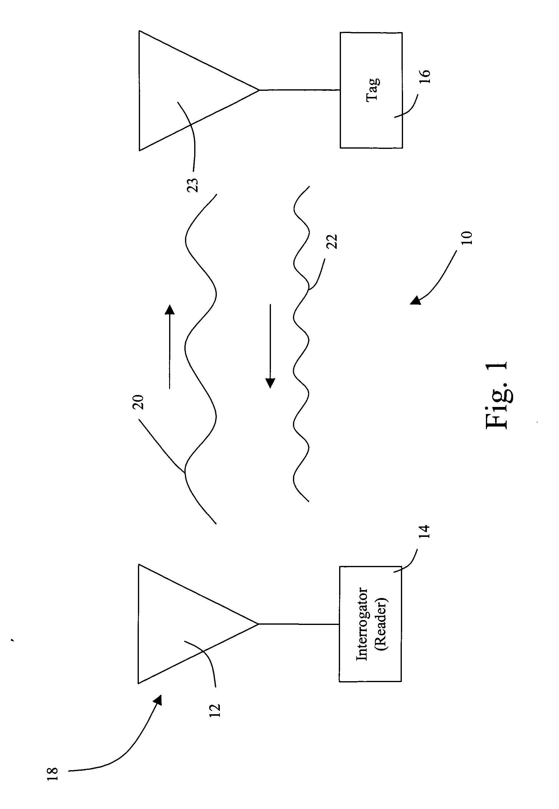
[0020] FIG. 1 is a diagram of an RF tag system.

Problems solved by technology

Several disadvantages may be associated with encoding a signal from an RFID tag by modulating the amplitude of a signal in some time varying fashion.

Method used


Image

  • Remote communication device and system for communication
  • Remote communication device and system for communication
  • Remote communication device and system for communication

Examples


example 1

[0058] For example, FIG. 3 shows a frequency hopping scheme of one embodiment of the present invention. In this embodiment of the present invention, the remote communication device has been modulating at 2.000 MHz and has an identification bandwidth from 2.032 MHz to 1.968 MHz. The remote communication device can be instructed to modulate the antenna at one of five prescribed frequencies, in steps of about 16 kHz up and down the band from 2.000 MHz. Each change in frequency corresponds to two bits of binary information according to the following scheme: +16 kHz=01; +32 kHZ=00; -16 kHz=10; -32 kHz=11. As a result, in this Example, n is 2 and the modulation frequency is 2.000 MHz. Note, the difference between each encoding frequency may not be exactly a multiple of 16 kHz. Since a change from one encoding frequency to another encoding frequency were made by shifting the secondary frequency some percentage up or down, this causes steps to a higher frequency to be larger than steps to l...

example 2

[0060] In another example, a remote communication device has been modulating at 2.000 MHz. It is instructed to modulate the antenna at one of five prescribed frequencies, in steps of about 8 kHz up and down the band from 2.000 MHz. Each change in frequency corresponds to two bits of binary information according to the following scheme: +8 kHz=01; +16 kHz=00; -8 kHz=10; -16 kHz=11. Since a change from one encoding frequency to another encoding frequency were made by shifting the secondary frequency some percentage up or down, this causes steps to a higher frequency to be larger than steps to lower frequencies.

[0061] Similar to the procedure described in Example 1, a jump at 1 ms from 2.000 MHz to 2.008 MHz corresponds to the two bits "01", a second jump up 16 kHz at 2 ms corresponds to the data set "00", and so forth. The cycle of five frequencies is repeating and allows the remote communication device to scroll through the encoding frequencies within the identification bandwidth ass...


PUM


Abstract

The present invention provides a remote communication device (i.e., radio frequency identification (RFID) tag) and system for communicating between one or more RFID tags and a reader using a frequency modulation method to encode binary data.

Description

STATEMENT OF RELATED APPLICATION[0001] The present application claims priority under 35 U.S.C. .sctn.119(e) from U.S. Provisional Application Ser. No. 60 / 476,541, filed Jun. 6, 2003, entitled "Frequency Hopping RFID Tags," the disclosure of which is incorporated herein by reference.[0002] The present invention relates to radio frequency (RF) devices and systems for communicating between one or more RF devices and a reader.[0003] Remote communication using wireless equipment may rely on radio frequency (RF) technology. One application of RF technology is in locating, identifying, and tracking objects, such as animals, inventory, and vehicles. Other applications of RF technology may include communication of data collected from remote sensors.[0004] RF identification (RFID) tag systems have been developed to facilitate monitoring of remote objects and communication of data collected from remote sensors. As shown in FIG. 1, a basic RF tag system 10 may include three components, an anten...

Claims


Application Information

Patent Timeline
Patent Type & Authority Applications(United States)
IPC IPC(8): G06K7/00G06K19/07
CPCG06K7/0008G06K7/10069G06K19/0717G06K19/0723
Inventor KRANZ, MARK J.
Owner STEMCO PROD INC
Learn More