Housing Case, Method for Manufacturing Housing Case, and Glass Insert Molding Die Used in Same

a housing case and glass insert technology, applied in the direction of casings/cabinets/drawers casings with display/control units, etc., can solve the problems of hard coating layer, small electric devices and communication devices, such as digital audio players and mobile phones, that are often subject to impact on their surfaces and other problems

Active Publication Date: 2010-01-21
NISSHA PRINTING COMPANY
View PDF10 Cites 98 Cited by
  • Summary
  • Abstract
  • Description
  • Claims
  • Application Information

AI Technical Summary

Benefits of technology

[0121]Examples, of the values in the above embodiments will be described below, but the scope of the invention is not limited thereto.

Problems solved by technology

Small electric devices and communication devices, such as a digital audio player and a mobile phone, which can be placed in clothing or in a bag and carried, are often subject to impact on their surfaces when they are accidentally dropped or hit with other articles in the bag.
The hard coat layer 103 comprising a thin coated film, however, is not hard enough as the front portion of the housing case; in particular, the portion that covers an LCD or any other display screen where high hardness is required.

Method used


Image

  • Housing Case, Method for Manufacturing Housing Case, and Glass Insert Molding Die Used in Same
  • Housing Case, Method for Manufacturing Housing Case, and Glass Insert Molding Die Used in Same
  • Housing Case, Method for Manufacturing Housing Case, and Glass Insert Molding Die Used in Same

Examples


example 1

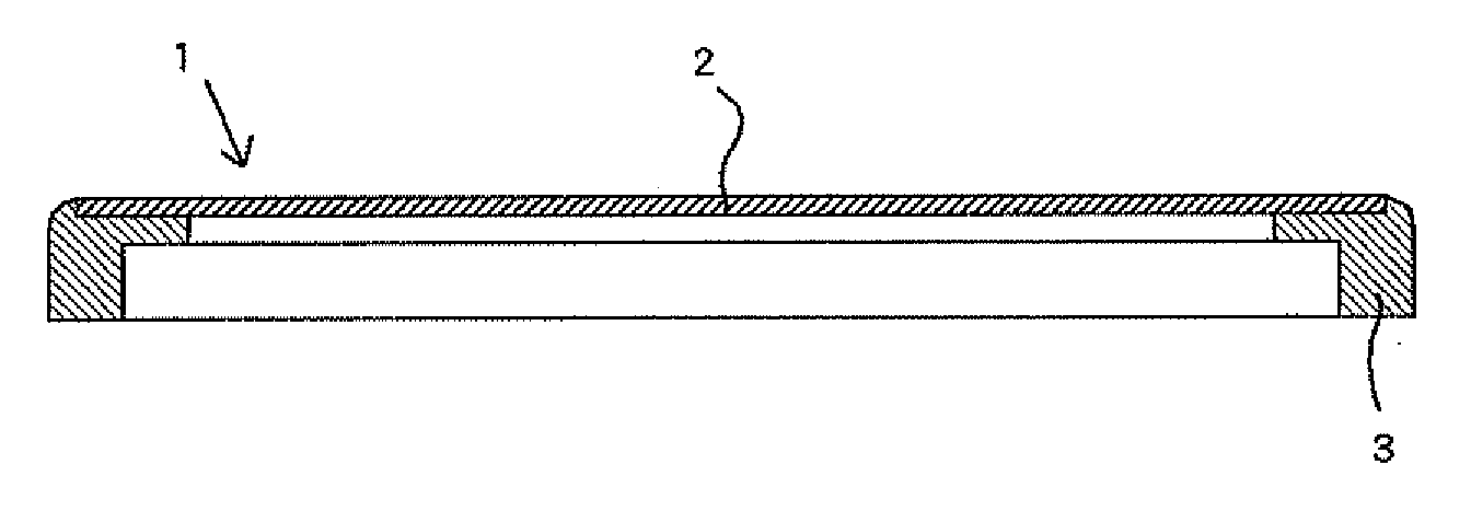
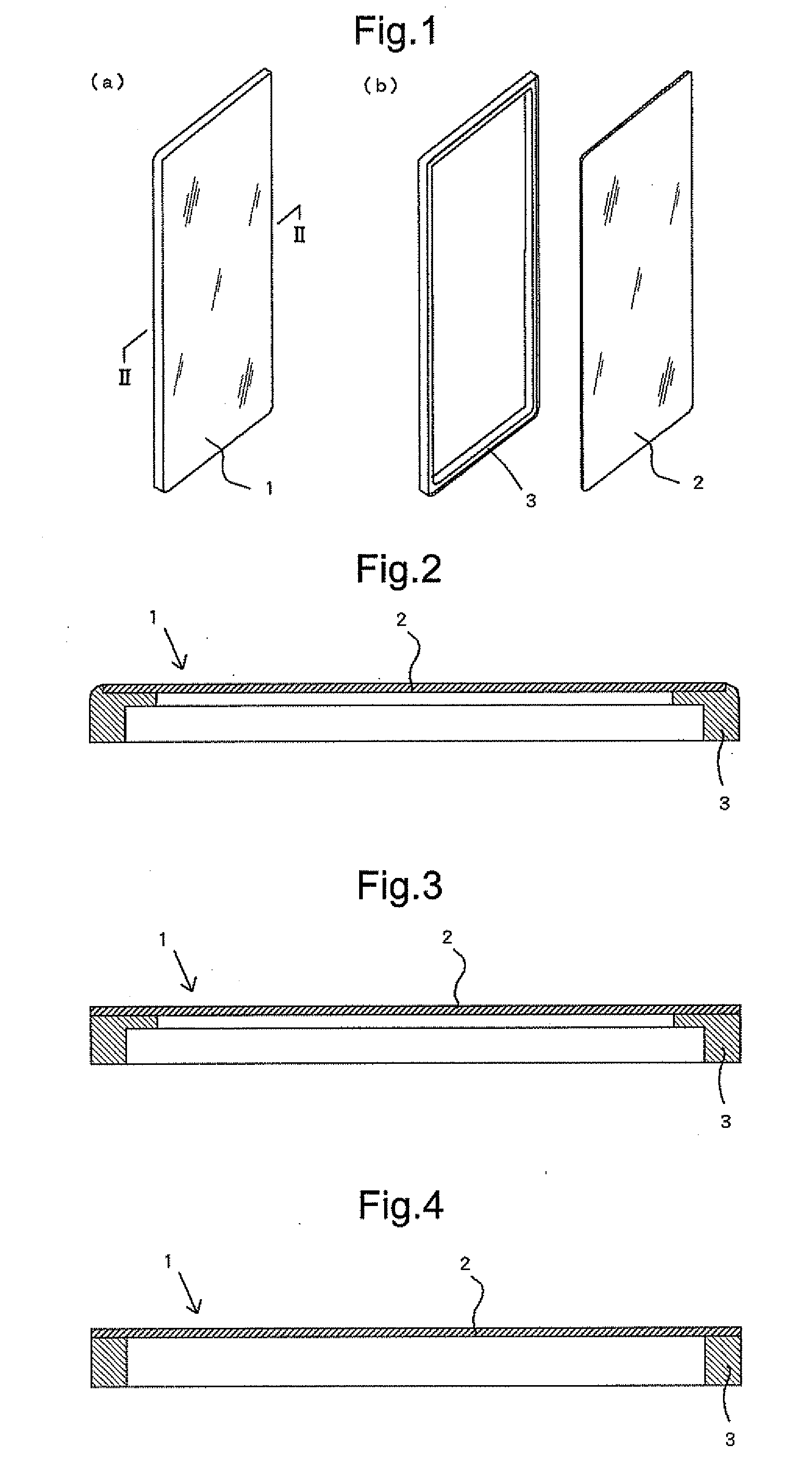
[0122]A glass plate of 88 mm in length, 38 mm in width, and 1 mm in thickness was prepared, and a circular opening for an operation panel was provided in the glass plate. A decorative layer was then formed on one side of the glass plate except a display window for a liquid crystal screen by using screen printing along with an ink containing a coloring agent and a polyester resin as a binder. An adhesive layer for glass made of a polyester resin, a primer layer made of a polyester resin, and an adhesive layer for resin made of a vinyl chloride / vinyl acetate / acrylic resin were then sequentially formed on the entire periphery of the undecorated side of the glass plate by using screen printing. A flat plate was thus obtained.

[0123]The flat plate was introduced into a molding die comprising a movable die and a stationary die, and secured in a predetermined position on the cavity surface through vacuum suction. After the molding die was closed, a molten polyacrylic resin was injected thro...

example 2

[0124]A glass plate of 88 mm in length, 38 mm in width, and 1 mm in thickness was prepared, and a circular opening for an operation panel was provided in the glass plate. A decorative layer / adhesive layer for glass was then formed on one side of the glass plate except a display window for a liquid crystal screen by using screen printing along with an ink containing a coloring agent and a polyester resin as a binder. A primer layer made of a polyester resin and an adhesive layer for resin made of a vinyl chloride / vinyl acetate / acrylic resin were then sequentially formed on the entire periphery of the decorated side of the glass plate by using screen printing. A flat plate was thus obtained.

[0125]The flat plate was introduced into the molding die comprising the movable die and the stationary die, and secured in a predetermined position on the cavity surface through vacuum suction. After the molding die was closed, a molten polyacrylic resin was injected through the gate to fill the ca...

example 3

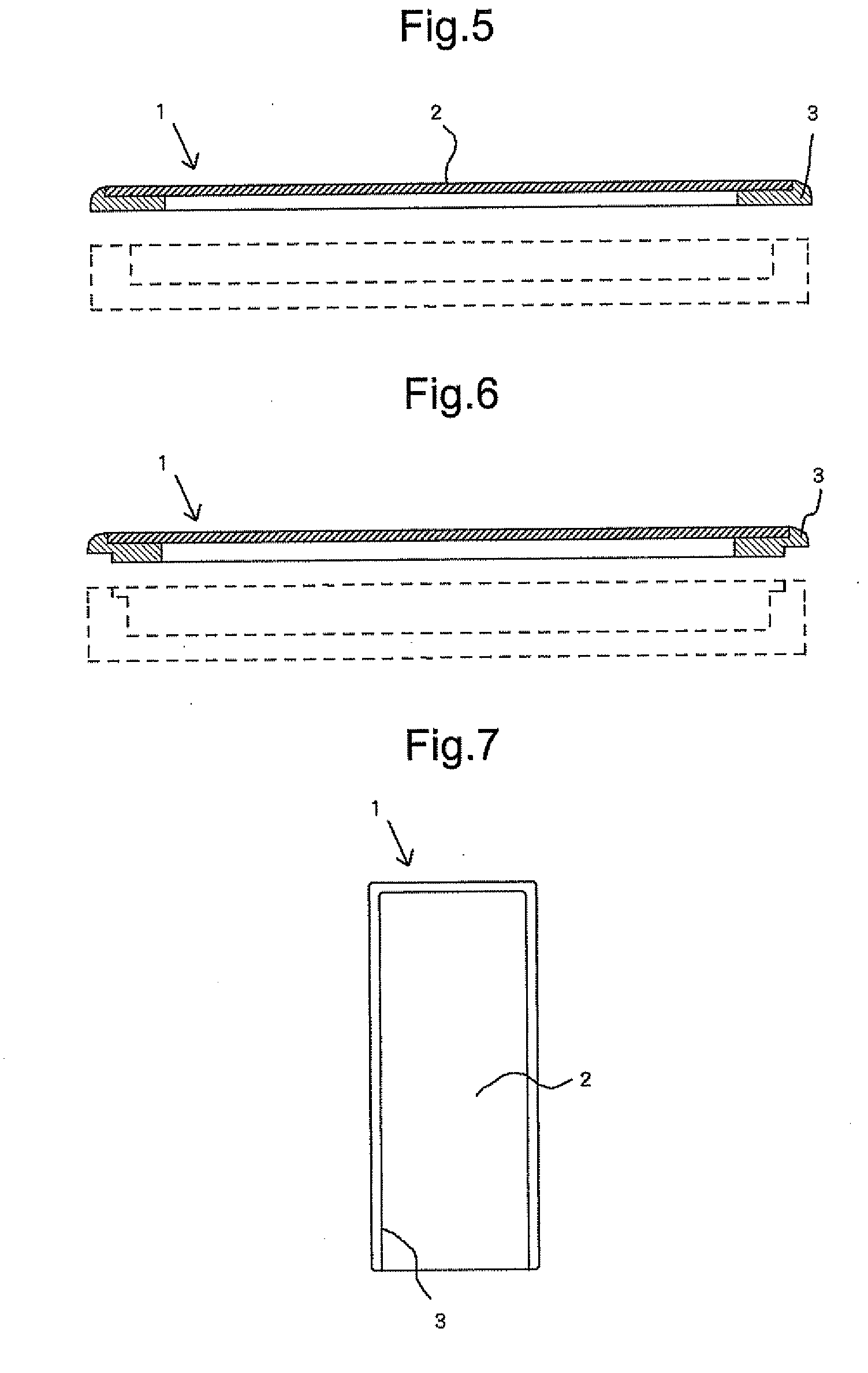
[0126]Example 3 only differs from Example 1 in that the adhesive layer for glass, the primer layer, and the adhesive layer for resin were sequentially formed on not only the periphery of the glass plate but also the entire surrounding portion of the opening in the undecorated surface of the flat plate to form a flat plate; a rectangular resin frame and a circular opening resin frame were formed by using injection molding; and at the same time, the resin frame and the opening resin frame were bonded to the undecorated surface of the flat plate with the adhesive layer for resin, the primer layer, the adhesive layer for glass interposed between the resin frames and the undecorated surface of the flat plate.


PUM

PropertyMeasurementUnit
molding shrinkage rateaaaaaaaaaa
thicknessaaaaaaaaaa
thicknessaaaaaaaaaa

Abstract

A housing case for a small electric device and communication device includes a flat plate having a dimension substantially the same as that of the front portion of the housing case and comprising at least a glass plate, and a resin frame integrated with the flat plate to support the backside periphery of the flat plate.

Description

TECHNICAL FIELD[0001]The present invention relates to a housing case for a small electric device and communication device, the front portion of the housing case; in particular, the portion of the housing case that covers an LCD or any other display screen having been adequately hardened, and also relates to a method for manufacturing the housing case and a glass insert molding die used in the same.BACKGROUND ART[0002]Small electric devices and communication devices, such as a digital audio player and a mobile phone, which can be placed in clothing or in a bag and carried, are often subject to impact on their surfaces when they are accidentally dropped or hit with other articles in the bag.[0003]To address the problem, the housing case of such a device needs to have a highly robust hard coat layer coated on the front portion of the housing case; in particular, the portion that covers an LCD or any other display screen, in order to enhance scratch resistance. For example, Patent Docum...

Claims


Application Information

Patent Timeline
Patent Type & Authority Applications(United States)
IPC IPC(8): H05K5/03B29C33/00C03C17/00
CPCB29C45/14073B29C45/14688B29C45/14778B29C45/401B29C2045/14155H05K5/0017B29L2031/3431B29L2031/445H04M1/0266H04M1/0283B29K2709/08C03B11/06H05K5/0217
Inventor NISHIMURA, TAKESHI
Owner NISSHA PRINTING COMPANY
Why Eureka
Try Eureka