
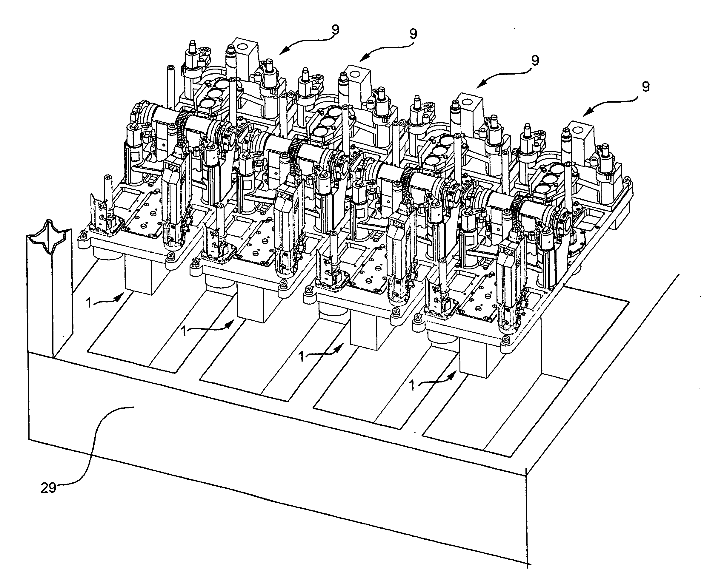
Forming section of a hollow glass items production machine and relevant support structure

a production machine and production machine technology, applied in glass making apparatus, glass blowing apparatus, glass shaping apparatus, etc., can solve the problems of increasing production time and cost, and increasing the final production cost of the section, so as to achieve straightforward and low-cost

Inactive Publication Date: 2010-01-28
BOTTERO SPA
View PDF2 Cites 8 Cited by
  • Summary
  • Abstract
  • Description
  • Claims
  • Application Information

AI Technical Summary

Benefits of technology

The present invention provides a forming section of a machine for producing hollow glass items that is designed to be straightforward, low-cost, and easy to use. The forming section includes a rough mold, a finish mold, handling means for the molds, first transfer means for transferring glass from the rough mold to the finish mold, second transfer means for extracting glass items from the finish mold, guiding means for the glass mass, closing means for the molds, and punching and blowing pneumatic means. The forming section is supported by a hollow support structure that includes a bottom hollow frame and a top support plate that can be easily removed. The invention also provides a hollow support structure for the forming section that includes a bottom hollow frame and a single top bored plate that can be releasably connected to the bottom hollow frame and adapted to support the glass items forming means.

Problems solved by technology

Though widely used, known sections of the above type are increasingly unsatisfactory, especially in terms of production cost, assembly time and replacement and / or production changeover time.
Moreover, because of the way in which the assemblies / mechanisms are connected to the parallelepiped supporting body underneath, the time taken to reassemble or reconfigure the section is no longer acceptable.
Finally, connecting the assemblies / mechanisms to the parallelepiped body underneath, and connecting the parallelepiped body to those of the adjacent sections necessarily call for precise machining of the molded or welded parallelepiped body, thus further increasing production time and cost and the final production cost of the section.

Method used


Image

  • Forming section of a hollow glass items production machine and relevant support structure
  • Forming section of a hollow glass items production machine and relevant support structure
  • Forming section of a hollow glass items production machine and relevant support structure

Examples


Embodiment Construction

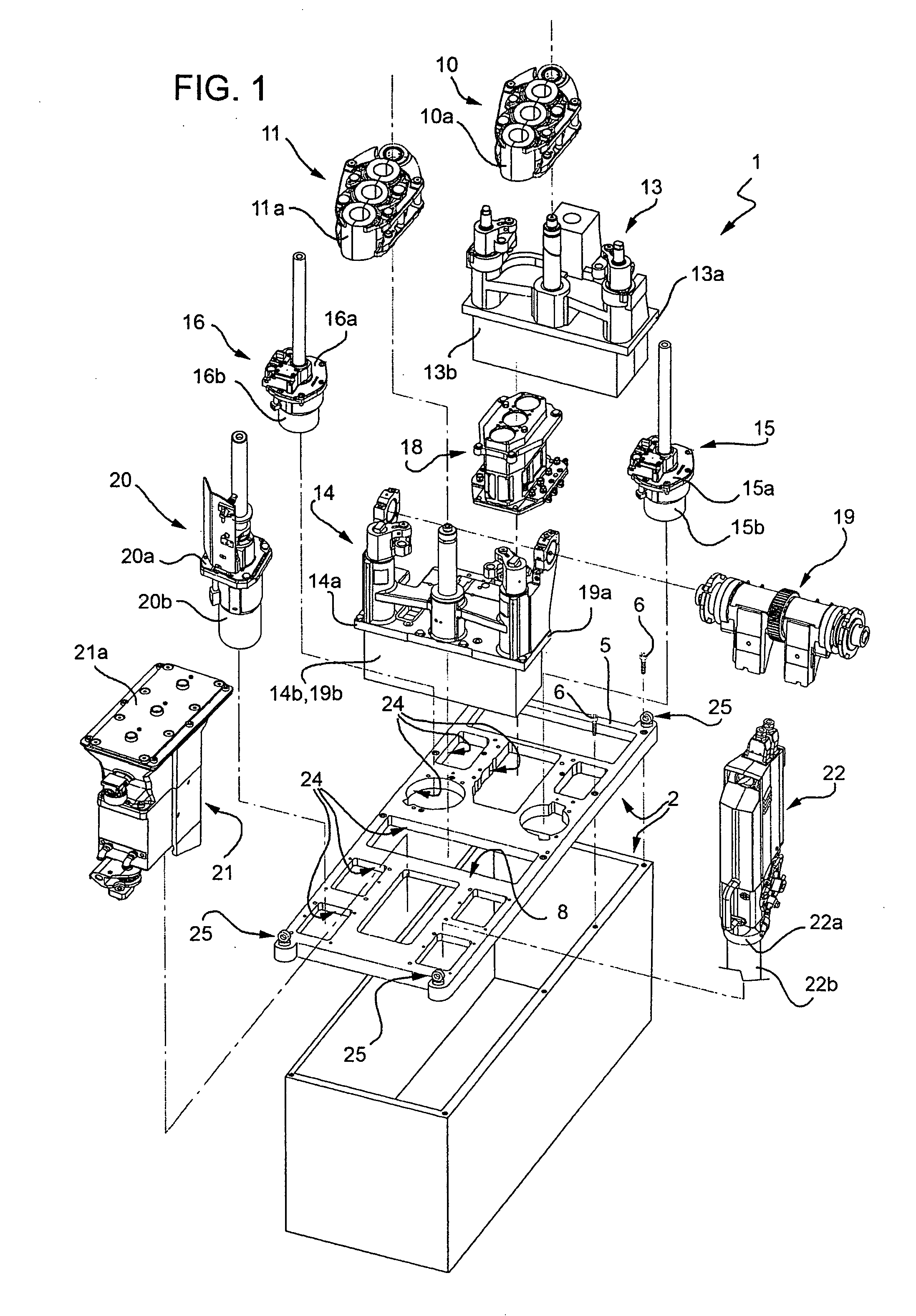
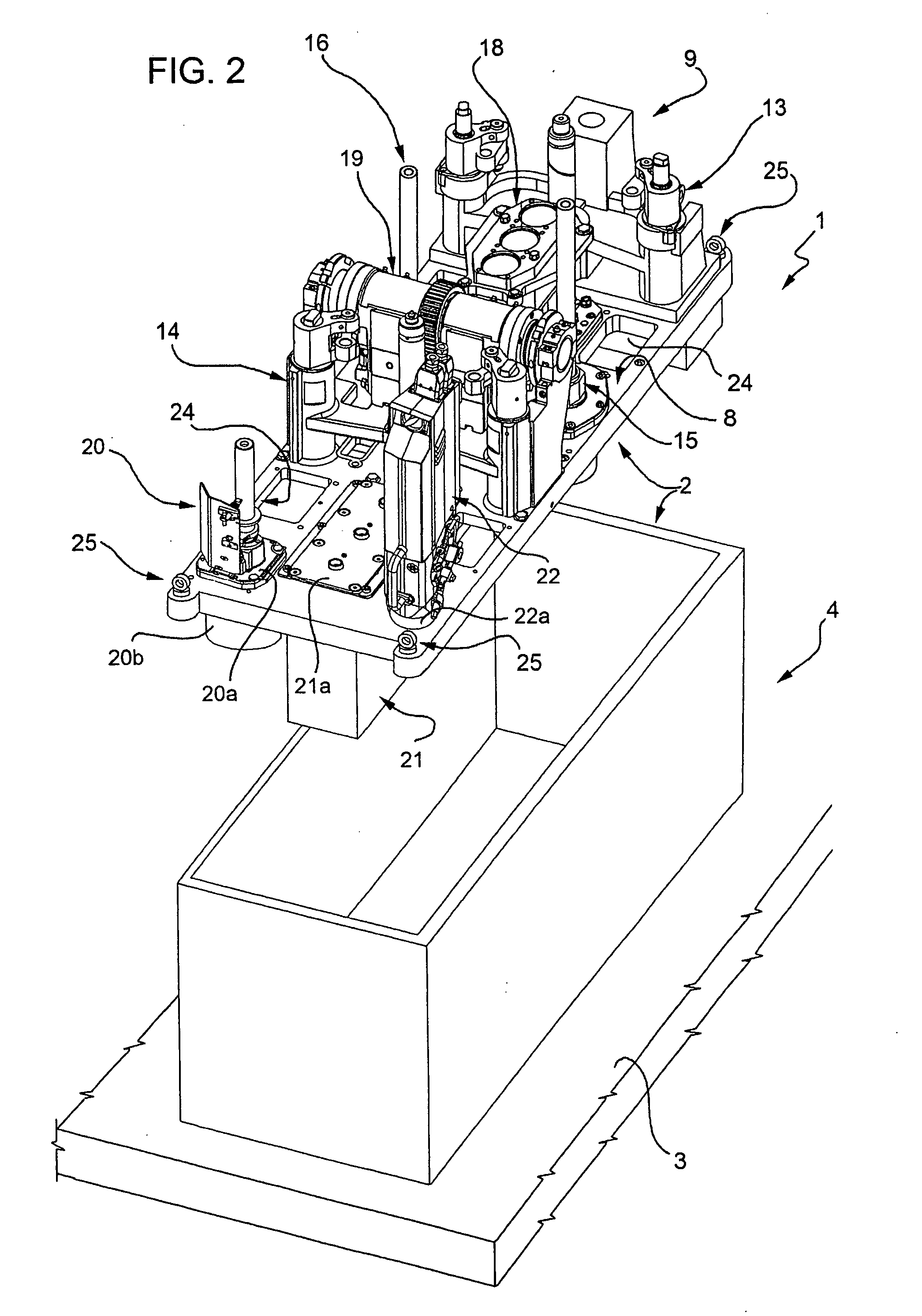
[0018]Number 1 in the accompanying drawings indicates as a whole a forming section of a machine for producing hollow glass items.

[0019]As shown in FIGS. 1 and 2, section 1 comprises a support structure 2 positioned, in use, on a shared base 3 (shown partly) of the machine, and in turn comprising a bottom frame, conveniently defined by a hollow one-piece parallelepiped body 4, and a single top supporting and connecting plate 5. In the example described, plate 5 is formed in one piece, and simply rests on hollow body 4 underneath, to which it is connected releasably by a number of screws 6 screwed and unscrewed from the top of section 1. Alternatively, in a variation not shown, plate 5 is connected to bottom hollow body 4 by a fast-fit connecting device.

[0020]Plate 5 defines a supporting surface 8 for an assembly 9 of component parts (FIG. 2) for producing or forming items from insertion of a glass gob to extraction of the finished item.

[0021]With reference to FIGS. 1 and 2, assembly ...


PUM

PropertyMeasurementUnit
massaaaaaaaaaa
timeaaaaaaaaaa
structural stabilityaaaaaaaaaa

Abstract

In a machine for forming glass items, a forming section has a forming assembly, and a bottom support structure for supporting the forming assembly. The forming section has a rough mold; a finish mold; a transfer assembly for transferring at least one glass mass being formed from the rough mold to the finish mold; an extractor for extracting at least one glass item from the finish mold; a glass mass guide device, a mold closing device, and a punching device associated with the rough mold. The forming section also has and a pneumatic blower device and a cooling device associated with at least the finish mold The bottom support structure has a bottom hollow frame, and at least one top plate separate from the bottom frame and on which the whole forming assembly rests and is connected.

Description

[0001]The present invention relates to a forming section of a machine for producing hollow glass items.BACKGROUND OF THE INVENTION[0002]Glass items are known to be formed using what are commonly known as I.S. forming machines, which comprise a number of forming sections, each operating independently of the others to form a respective succession of glass items.[0003]Accordingly, each forming section comprises a rough mold assembly and a finish mold assembly, each comprising a mold, a respective mold opening / closing device, and a respective mold cooling assembly. Each forming section also comprises a handling assembly for removing the glass items from the rough mold and transferring them to the finish mold; and a handling assembly for removing the items from the finish mold and depositing them onto a supporting surface, from which they are then transferred by a push assembly onto a common unloading conveyor. Each section also comprises a number of forming mechanisms associated with th...

Claims


Application Information

Patent Timeline
Patent Type & Authority Applications(United States)
IPC IPC(8): C03B11/00C03B9/00
CPCC03B9/16C03B9/165C03B9/453C03B9/1932C03B9/193
Inventor BALBI, MARIO
Owner BOTTERO SPA
Learn More