Method for implementing a correct winding of a wire on a spool

a technology of wire winding and spool, which is applied in the direction of thin material handling, filament handling, transportation and packaging, etc., can solve the problems of wire dispensing irregularities, flange deformation during the progressive filling of the spool, and the inertia of the wire is difficult to control, so as to prevent accidental damage to the machine

Inactive Publication Date: 2017-01-19
SAMP CON UNICO SOCIO
View PDF7 Cites 3 Cited by
  • Summary
  • Abstract
  • Description
  • Claims
  • Application Information

AI Technical Summary

Benefits of technology

[0016]Therefore, the object of the present invention is to provide a method for implementing a correct winding of a wire on a spool, which is designed to eliminate the aforementioned drawbacks and, at the same time, can be manufactured in a straightforward and low-cost manner.
[0034]In the presence of a valley or a peak and, therefore, of an instantaneous variation of the wire winding diameter compared to the servodiameter, the dancer moves, thus generating a variation of the position signal, which is interpreted as a presence of a peak or valley, which, hence, causes a variation of the displacement speed of the wire dispensing device.
[0039]In this case, the wire is wound in the same spot, thus piling up (crating the so-called “rough”), and, therefore, the dancer changes its angular position and the correlation between the position of the dancer and the displacement speed of the wire dispensing device allows the machine to stop, so as to avoid producing rejected items and so as to preserve the machine from accidental damages caused by the braking of the wire after it has piled up.

Problems solved by technology

Furthermore, the flanges can also deform during the progressive filling of the spool due to the thrust exerted by the wire hank.
Other causes for the formation of peaks and valleys can be, for example, a loosening and / or a delay in the movement of the wire due to an inversion of the direction of movement of the wire dispensing device, or possible wire dispensing irregularities due to the size; for example, a wire with a fairly large diameter tends to have an inertia that is hard to control.
Even if the system described in U.S. Pat. No. 7,370,823 B2 (NIEHOFF) allows operators to control the winding of the wire on the spool in a fairly precise manner, it turns out to be expensive and sometimes not very reliable because of the controls carried out by means of speed sensors.

Method used


Image

  • Method for implementing a correct winding of a wire on a spool
  • Method for implementing a correct winding of a wire on a spool

Examples


Embodiment Construction

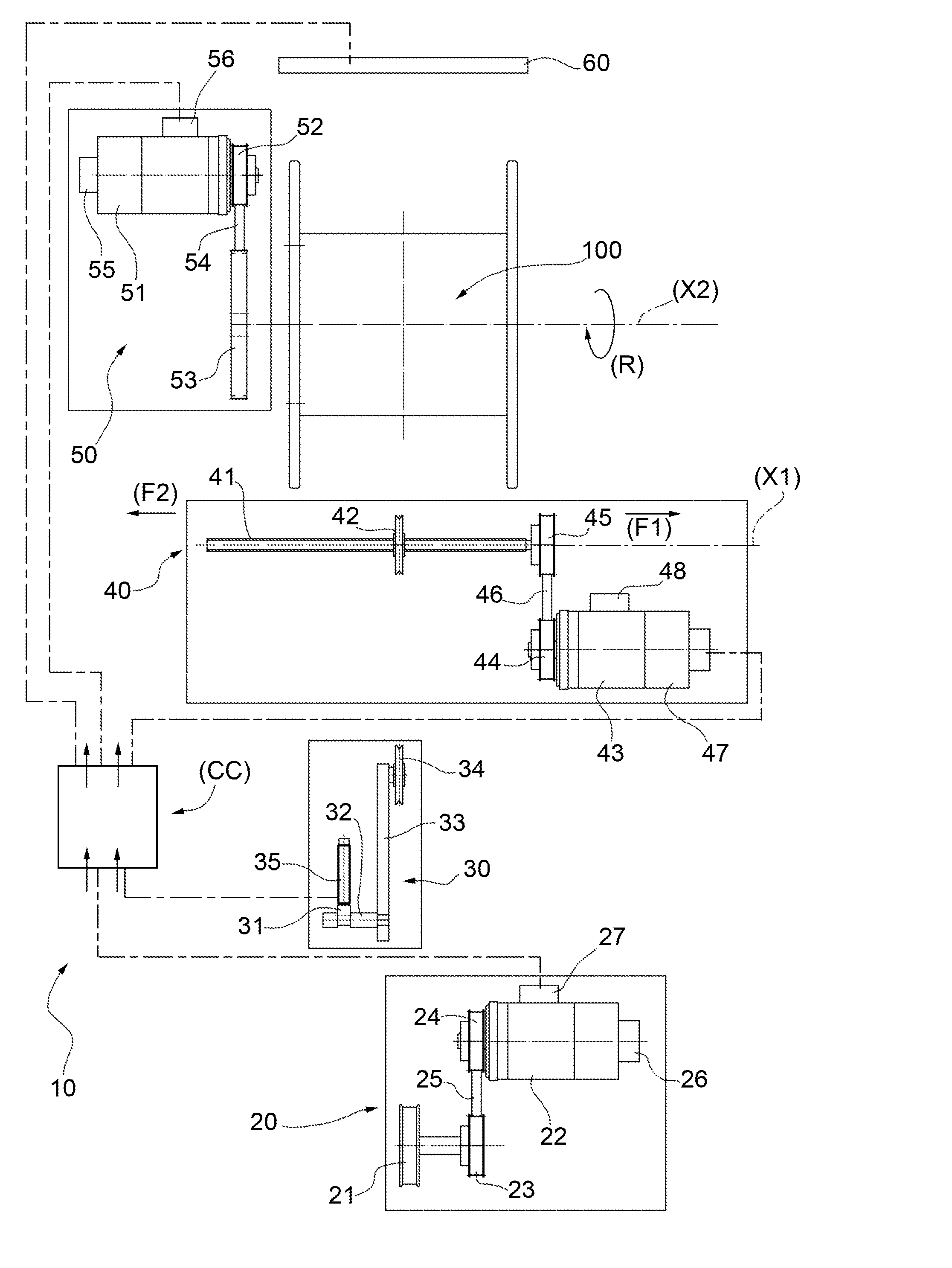
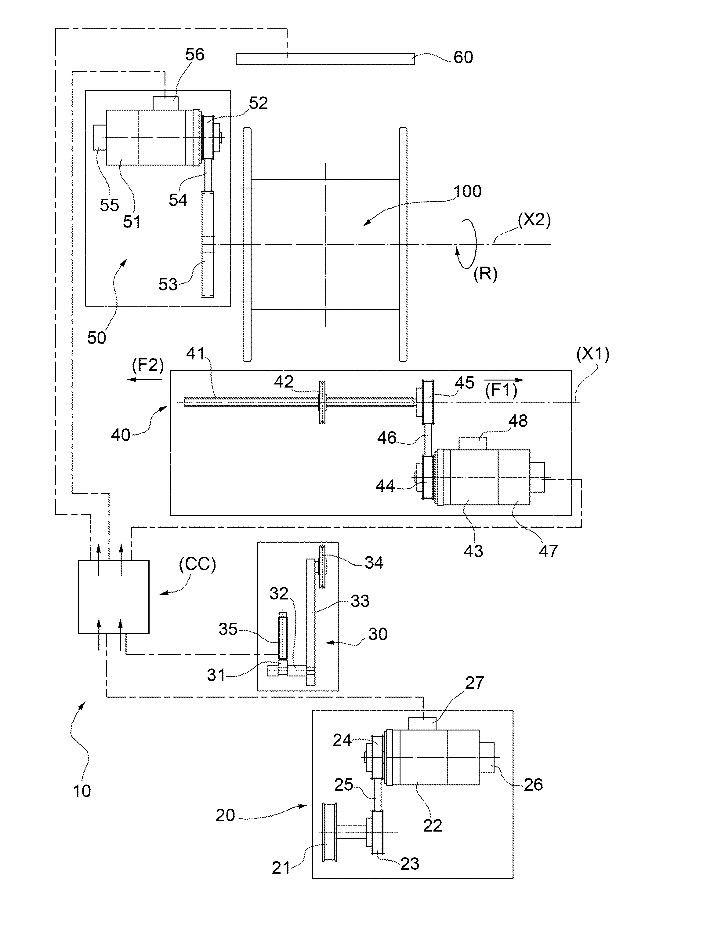
[0042]In the accompanying figure, number 10 indicates a machine to wind a wire on a spool 100, on which the method according to the present invention can be implemented.

[0043]The machine 10 comprises the following devices arranged in line:

[0044](a) a feeding device 20 to feed a wire (not shown) to be wound around a spool 100; this feeding device 20 comprises, as it is known, a drawing die 21, which is caused to rotate by a synchronous electric motor 22 (for example, a brushless motor) by means of a pair of wheels 23, 24, which are connected to each other by a belt 25; the synchronous electric motor 22 is associated with a relative encoder 26 and is controlled by an electronic board 27;

[0045](b) a dancer 30 comprising, in turn, a cam 31, which is mounted on a shaft 32, which pivots on a lever 33, on which there is mounted, in a rotary manner, a wire transmission pulley 34; the sensor 35 is not in contact with the surface of the cam 31; the sensor 35 provides an analogical signal, whi...


PUM


Abstract

Method for implementing a correct winding of a wire on a spool (100). The method also comprises a step for calculating the angular speed of a motor (43) displacing the wire dispensing device (40) according to the wire winding step and according to the dancer error, detected by a position sensor (35) that provides an analogical signal with respect to a zero position and to a tolerance value, in order to determine the presence of a possible “valley error”, or of a possible “peak error”. In this method, if during the spool winding, a “valley error” or a “peak error” is detected, the control device decides whether to slow down or to increase the speed of the wire dispensing device (40) with the aim of filling the depression or skipping the peak.

Description

TECHNICAL FIELD[0001]The present invention relates to a method for implementing a correct winding of a wire on a spool.[0002]Incidentally, it should be pointed out that the “wire” defined herein might be an insulated or non-insulated metal wire, an insulated or non-insulated strand, a string, filaments, glass fibres and the like.STATE OF THE ART[0003]As it is known, peaks and valleys in a spool winding are caused by irregularities of the surfaces of the core of the spool, by the progressive overlapping of the layers of wound wire, by the loosening of spool winding stretch due to problems in the path of the wire, etc.[0004]The formation of peaks and valleys is also possible, furthermore, in the area of a flange of the spool due to an incorrect position of the flange itself; this is the case, for example, when the spool has an actual “spool winding working width” that is different from the pre-set one, taking into account the type of spool.[0005]The formation of peaks and valleys is a...

Claims


Application Information

Patent Timeline
Patent Type & Authority Applications(United States)
IPC IPC(8): B65H63/06B65H59/10B65H54/22
CPCB65H63/06B65H59/10B65H54/22B65H54/2878B65H2551/13B65H2557/11B65H2701/36
Inventor AFFATICATI, ARTEMIOCONTE, ENRICOCONTE, ROBERTO
Owner SAMP CON UNICO SOCIO
Why Eureka
Try Eureka