Method and assembly for cutting a molten glass rope on a glassware molding machine

a molding machine and glassware technology, applied in glass blowing equipment, glass making equipment, glass shaping equipment, etc., can solve the problems of unhealthy working environment, long time consumption, and inability to meet the needs of production,

Inactive Publication Date: 2009-10-15
BOTTERO SPA
View PDF5 Cites 4 Cited by
  • Summary
  • Abstract
  • Description
  • Claims
  • Application Information

AI Technical Summary

Benefits of technology

[0010]It is an object of the present invention to provide a method of cutting molten glass ropes, designed to provide a straightforward, low-cost solution to the above problems.

Problems solved by technology

Though widely used, the above method of cutting molten glass ropes is far from satisfactory, mainly on account of the cutters having to be sprayed with coolant.
In contact with the cutting assembly, part of the coolant is evaporated by the intense heat, and forms a thick vapour around the machine, thus making for an unhealthy working environment.
Because of the coolant, the sealing devices on the actuators of relatively moving parts, and all the sealing devices around the cutting assembly in general, operate in a highly aggressive environment and wear out relatively fast.
Finally, known cutting assemblies are structurally massive and of considerable weight.

Method used


Image

  • Method and assembly for cutting a molten glass rope on a glassware molding machine
  • Method and assembly for cutting a molten glass rope on a glassware molding machine
  • Method and assembly for cutting a molten glass rope on a glassware molding machine

Examples


Embodiment Construction

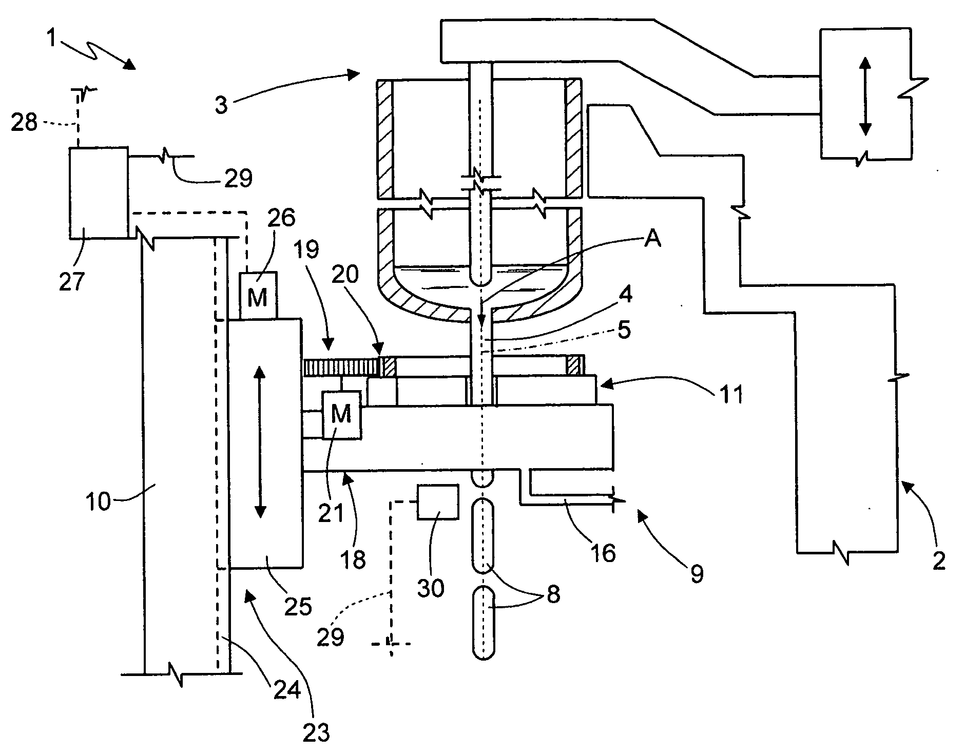
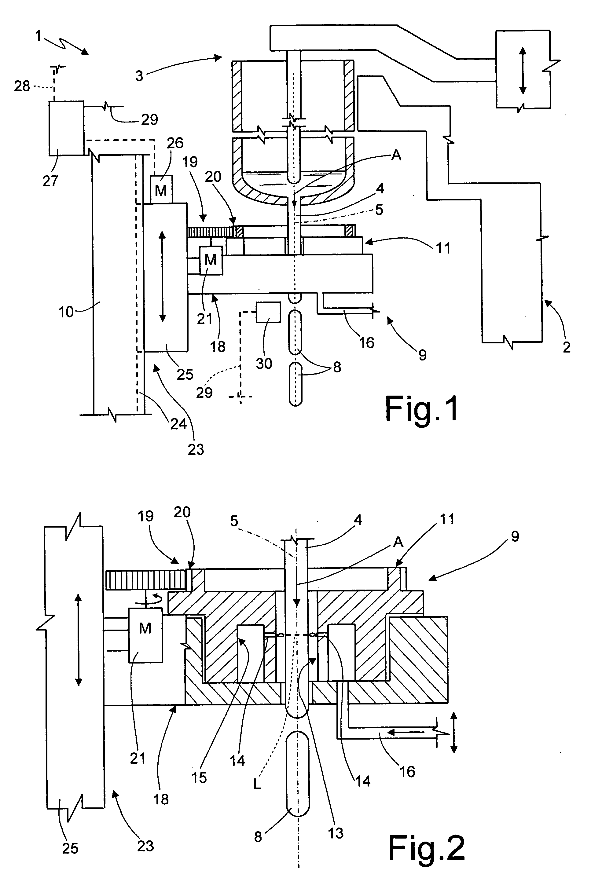
[0021]Number 1 in FIG. 1 indicates as a whole a so-called I.S. machine for molding glass, articles (not shown). Machine 1 comprises a frame 2, which supports an extruder 3 for forming a molten glass rope 4 having an axis 5 and fed in a straight direction A coincident with axis 5. On machine 1, molten glass rope 4 is cut crosswise along lines L into a succession of glass gobs 8 by a cutting assembly 9.

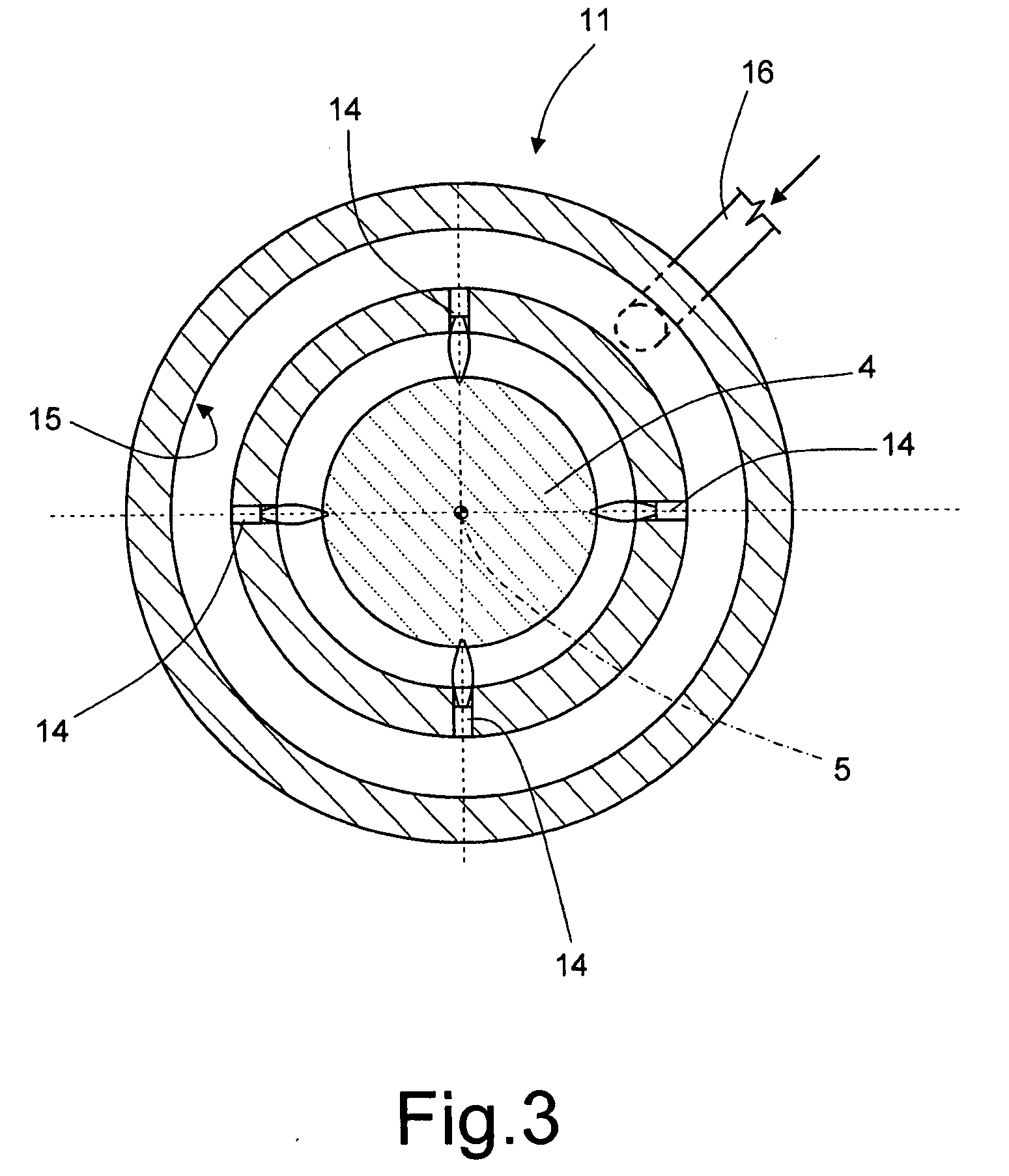
[0022]Cutting assembly 9 comprises a fixed mounting structure 10 connected integrally to frame 2 of machine 1; and a heating head 11 fitted to structure 10, as described in detail below, and surrounding rope 4 coaxially with axis 5. In the example shown, heating head 11 is bounded by a cylindrical inner surface 13, which extends coaxially with axis 5 of rope 4 and defines a loose passage for rope 4. At least two heat sources 14 extend partly through cylindrical surface 13 on diametrically opposite sides of rope 4 (FIG. 2). Here and hereinafter, the term “heat source” is intended to mean...


PUM

PropertyMeasurementUnit
viscosityaaaaaaaaaa
thermal energyaaaaaaaaaa
length of timeaaaaaaaaaa

Abstract

On a glassware molding machine, a molten glass rope travelling in a feed direction is cut crosswise into at least one glass gob by supplying thermal energy to the cutting portion of the rope by means of a heating head, so as to locally alter the viscosity of the rope and detach the gob.

Description

CROSS REFERENCE TO RELATED APPLICATIONS[0001]This application claims benefit under 35 U.S.C. §119(a) of Italian Patent Application No. TO2008A 000281 filed Apr. 11, 2008, the entire contents of which are incorporated herein by reference.BACKGROUND OF THE INVENTION[0002]1. Field of the Invention[0003]The present invention relates to a method and assembly for cutting a molten glass rope on a glassware molding machine.[0004]2. Description of Related Art[0005]In glassware molding, so-called I.S. molding machines are known, which comprise a forming assembly for forming a molten glass rope; and a cutting assembly, known as “parallel shears”, for mechanically cutting the rope crosswise into a succession of glass gobs. Accordingly, the cutting assembly comprises two shear-type cutters substantially facing each other and movable in opposite directions, perpendicularly to the travelling direction of the molten glass rope, between a withdrawn rest position, in which they let the rope through a...

Claims


Application Information

Patent Timeline
Patent Type & Authority Applications(United States)
IPC IPC(8): C03B7/10C03B21/02
CPCC03B7/005C03B7/12C03B7/10
Inventor BALBI, MARIO
Owner BOTTERO SPA
Why Eureka
Try Eureka