Baggage deposit system

Active Publication Date: 2010-01-28
SCARABEE ID
View PDF52 Cites 23 Cited by
  • Summary
  • Abstract
  • Description
  • Claims
  • Application Information

AI Technical Summary

Benefits of technology

[0008]It is an object of the present application to provide a sy

Problems solved by technology

To start with, that means wage costs.
In addition, it has the further disadvantage that many employees of different airlines or members of ground staff with a corresponding number of desks are required in order to be able to carry out the method.
On account of limited availability of desks and desk staff, long queues of waiting passengers can form.
Expansion of handling capacity is usually hampered by the available space at the airport.
In the case of this known system, however, supervision by airline staff or groun

Method used


Image

  • Baggage deposit system
  • Baggage deposit system
  • Baggage deposit system

Examples


first embodiment

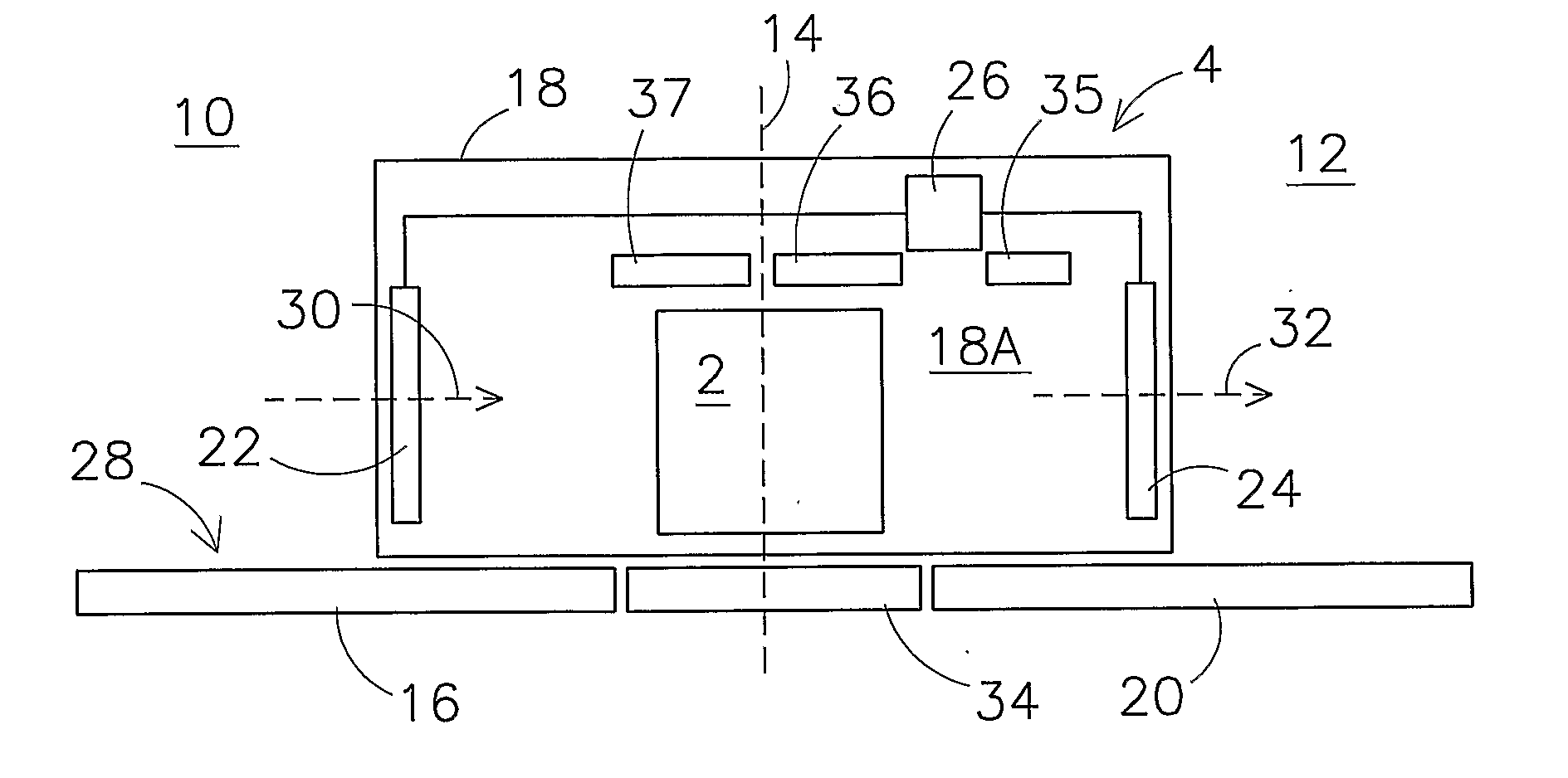
[0051]The same reference numerals refer to the same parts in the drawings. FIG. 1 shows a device 4 for receiving a piece of baggage 2, such as a suitcase, a travel bag, a box and / or any other suitable means for carrying materials such as baggage. The piece of baggage 2 is received from a passenger and is to be carried with the passenger to a destination in a means of transport such as an aircraft or a boat, bus or train. Of course, the device can also be used for other applications, such as for receiving articles for temporary storage in a depot or for receiving mail items or other articles for transport which are not being accompanied by the owner of the article.

[0052]The owner of the piece of baggage 2 can deposit his piece of baggage 2 at the device 4 in an area 10 which is accessible to the public, which device 4 receives the piece of baggage 2 and conveys it to a non-public area 12. The public area 10 and the non-public area 12 are separated, for example by means of a wall 14, ...

second embodiment

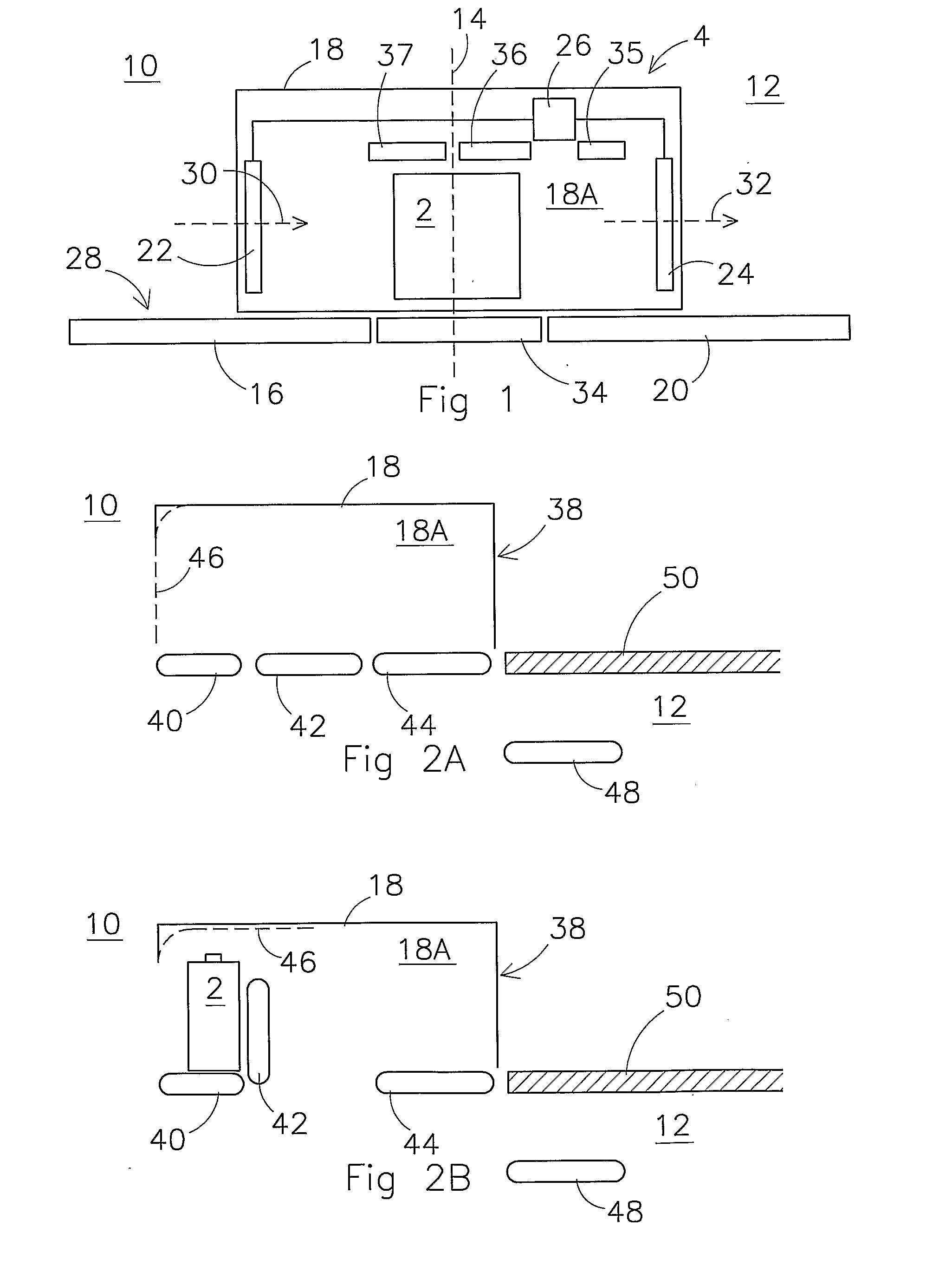
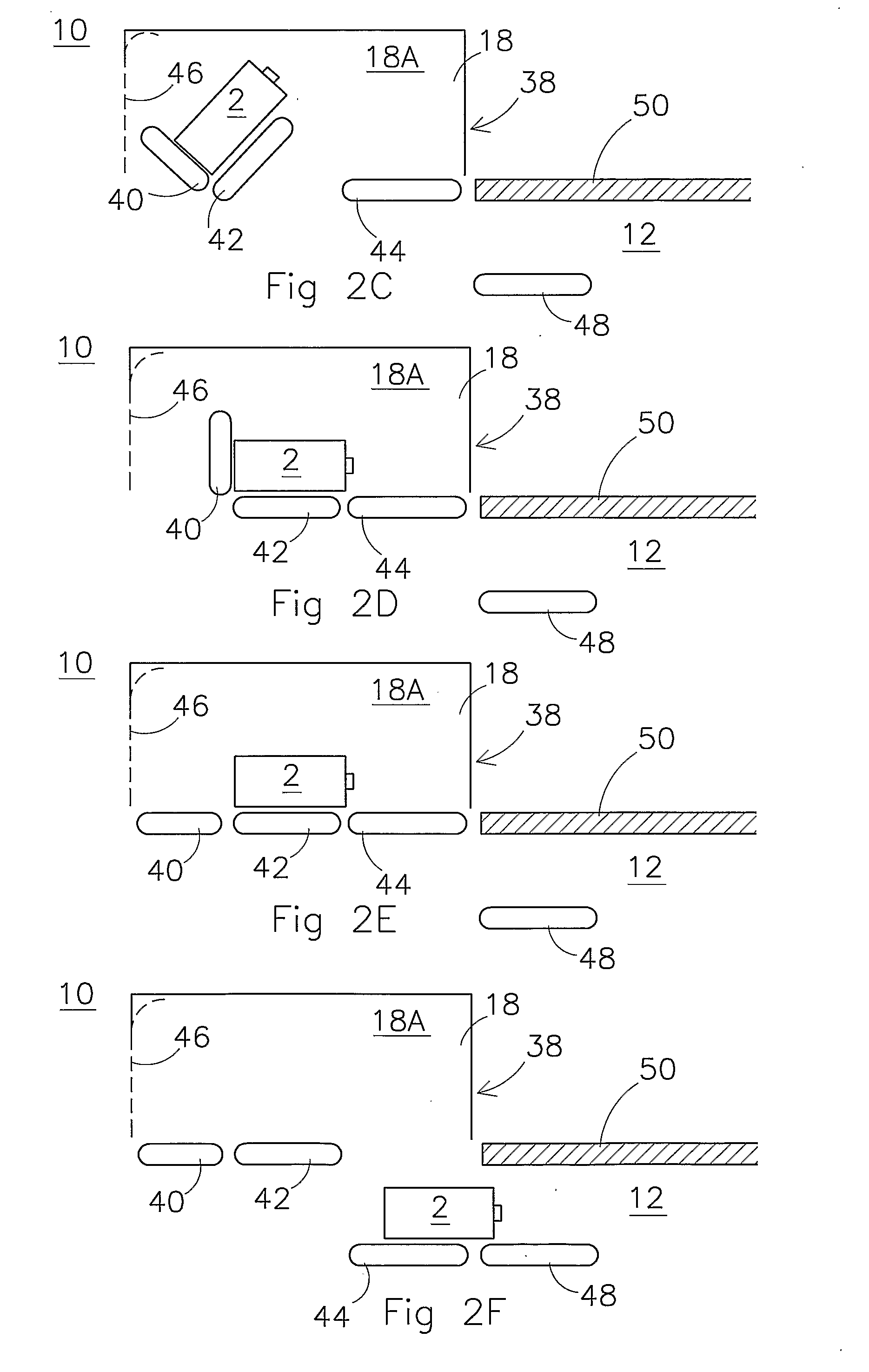
[0066]FIGS. 2A-2F show a device 38 according to the invention. Furthermore, FIGS. 2A-2F show an embodiment of a method according to the invention. The device 38 comprises a housing 18, inside which the receiving room 18A is situated. A first conveyor element 40, a second conveyor element 42 and a third conveyor element 44 are provided on the underside of the receiving room 18A. The first and second conveyor elements 40, 42 are fixed so that they tilt. The third conveyor element 44 also functions as a lifting device. The third conveyor element 44 can furthermore serve as a temporary storage facility (buffer). A temporary storage function is desirable, for example, if a passenger is permitted to feed in two or more pieces of baggage 2. If the infeed is broken off after the infeed of one or more pieces of baggage 2, said pieces of baggage 2 already fed in earlier must be returned to the passenger. The third conveyor element 44 can furthermore be designed as a temporary storage facility...


PUM


Abstract

In a device (4) for receiving a piece of baggage (2) for transport, for example at an airport, the device comprises a receiving room (18A) with an infeed opening and a discharge opening. The receiving room is provided with a closing assembly, the closing assembly comprising a closing mechanism (22, 24). The device furthermore comprises a conveyor unit (16, 20) for discharging the piece of baggage from the receiving room through the discharge opening. The closing assembly is equipped at any time to keep at least one or other of the infeed opening and the discharge opening closed. In this way a device according to the invention is equipped to protect deposited baggage from third parties and to prevent persons from following the piece of baggage to the areas not accessible to the public. The present invention also provides a method for receiving a piece of baggage, which method is in accordance with the functioning of the above-mentioned device.

Description

CROSS-REFERENCE TO RELATED APPLICATIONS:[0001]This application is the National Stage of International Application No. PCT / NL2008 / 000004, filed Jan. 7, 2008, which claims the benefit of Netherlands Application No. NL 1033178, filed Jan. 5, 2007, the contents of which is incorporated by reference herein.FIELD OF THE INVENTION[0002]The present invention relates to a baggage deposit system and a method for depositing baggage.BACKGROUND OF THE INVENTION[0003]At airports, passengers have to check in and deposit their baggage prior to their flight. Deposited baggage is furnished with a label and taken away on a conveyor system to a processing area. In the processing area the baggage is sorted on the basis of the affixed label, and is ultimately placed on board the correct aircraft.[0004]Until recently, an employee of the airline concerned or a member of the ground staff handled the checking in and depositing of the baggage. At the present time, passengers who are taking only hand baggage c...

Claims


Application Information

Patent Timeline
IPC IPC(8): B65G65/02B65G43/00H01J3/14H01J40/00
CPCB64F1/366
Inventor TAN, MICHAEL KIM
Owner SCARABEE ID
Why Eureka
Try Eureka