Molding method for an optical element and optical element molding apparatus

Inactive Publication Date: 2010-01-28
CANON KK
View PDF1 Cites 1 Cited by
  • Summary
  • Abstract
  • Description
  • Claims
  • Application Information

AI Technical Summary

Benefits of technology

[0011]It is an object of the present invention to provide a molding method for an optical element and an optical element molding apparatus in which an optical ele

Problems solved by technology

S63-140035, where the bearing is brought into point-contact with the upper and lower dies and the guide member, it is difficult to achieve the temperate follow-up of the bearing with respect to change in temperature of the upper and lower dies and the guide member.
Therefore, there has been a problem in that the temperature of the bearing at the time of heating and cooling and the temperatures of the guide member and the upper and lower dies are liable to be different from each other.

Method used


Image

  • Molding method for an optical element and optical element molding apparatus
  • Molding method for an optical element and optical element molding apparatus
  • Molding method for an optical element and optical element molding apparatus

Examples


embodiment 1

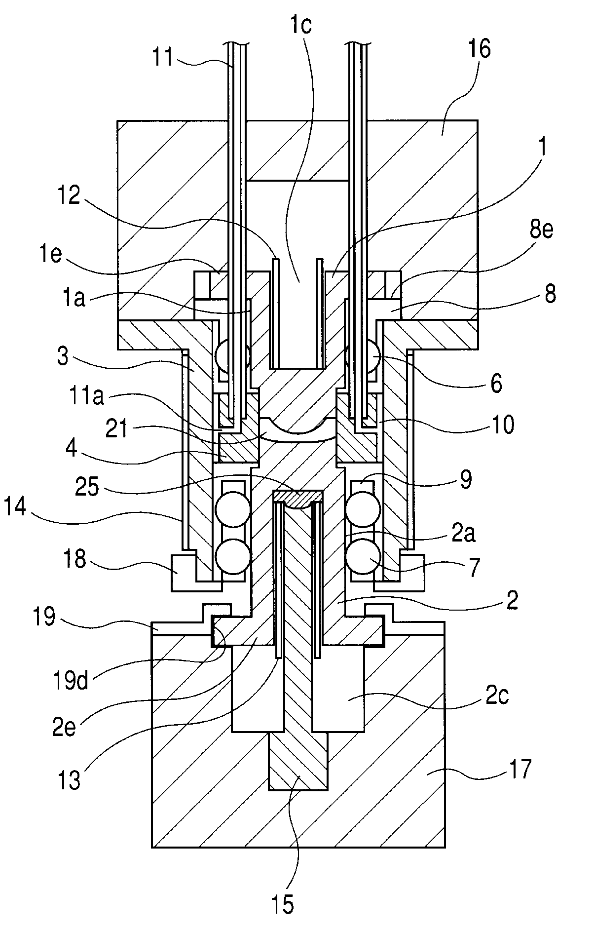
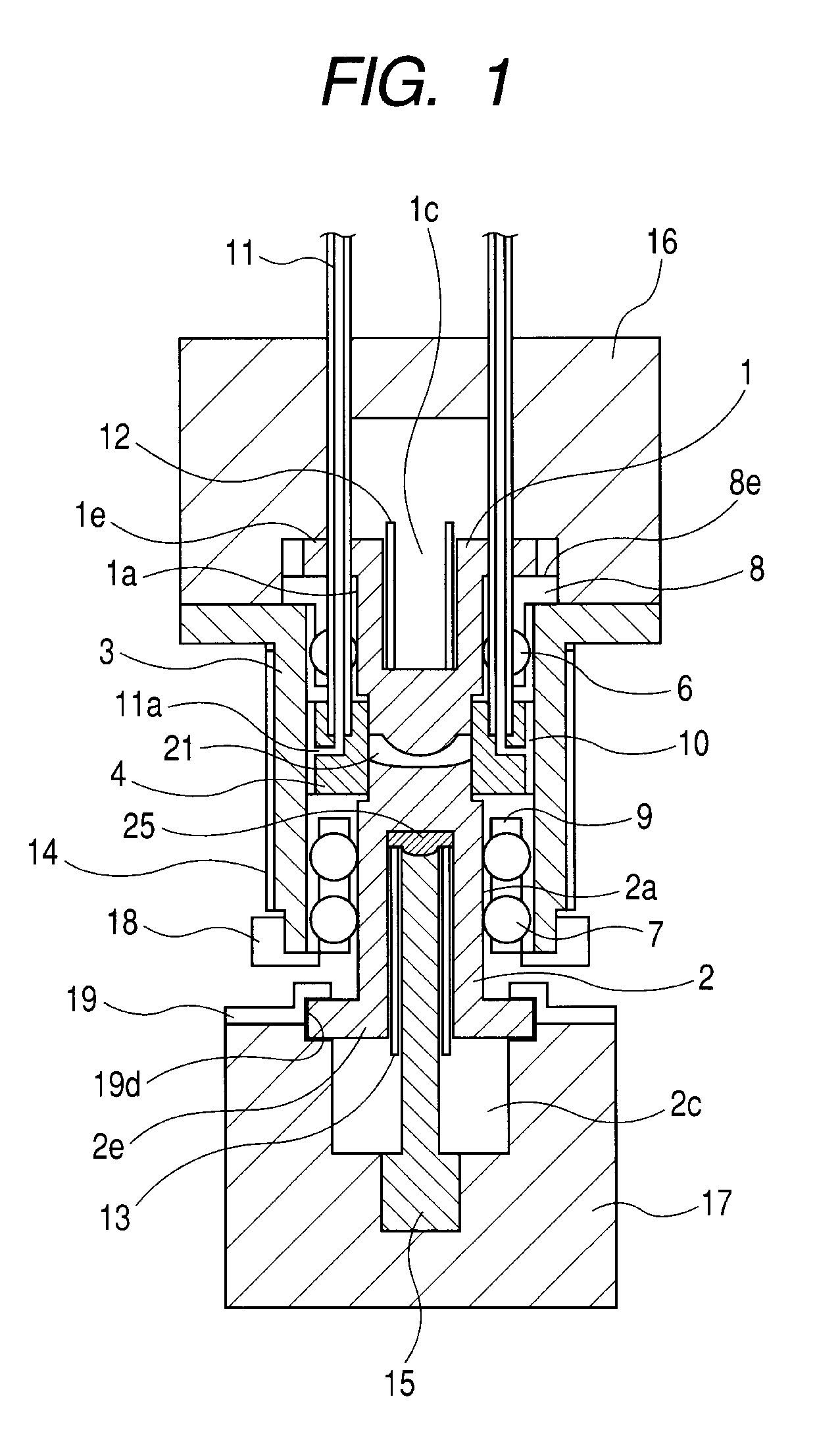
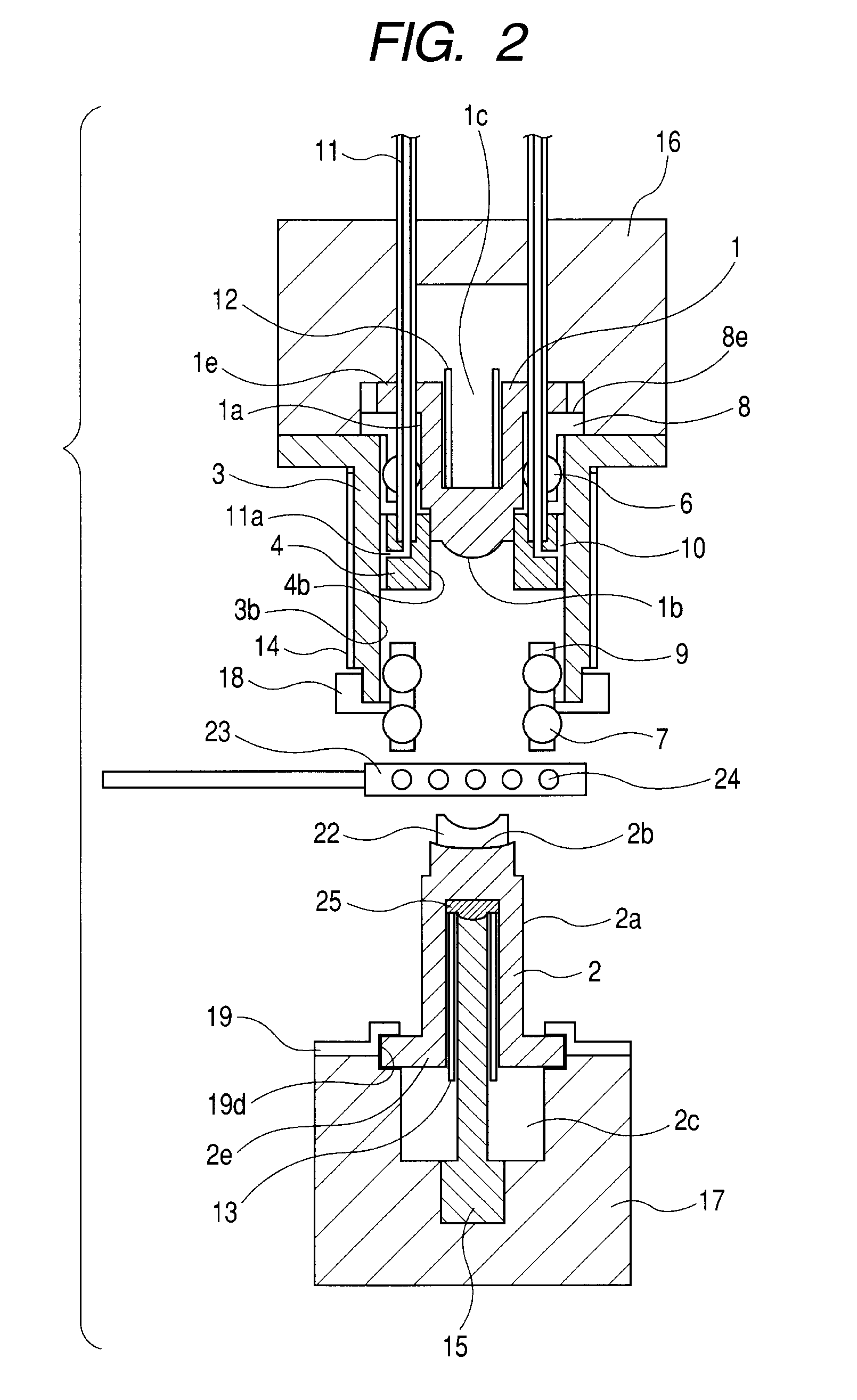
[0018]An optical element molding apparatus according to Embodiment 1 of the present invention is described with reference to FIGS. 1 and 2. FIG. 1 illustrates a state in which upper and lower dies are closed after a pressing operation, and FIG. 2 illustrates a state in which the upper and lower dies are opened and the upper and lower dies prior to pressing and a glass material (material) are heated.

[0019]An upper die member 1 and a lower die member 2 constituting the upper and lower dies have cylindrical surfaces 1a and 2a, respectively. A guide member 3 supports a ring-shaped side die member 4. On a lower portion of the upper die member 1, there is formed a molding surface 1b for transferring a shape of an optical surface of an optical element to the glass material. Similarly, on an upper portion of the lower die member 2, there is formed a molding surface 2b. Further, on the outer peripheral surface of the molding surface 1b of the upper die member 1, there is formed a flat portio...

example 1

[0058]With use of the optical element molding apparatus illustrated in FIGS. 1 and 2, a lens used in a camera was molded. The procedure is described in detail.

[0059]A biaspherical concave meniscus lens was molded with use of a glass material having a transition point of 510° C. The biaspherical concave meniscus lens had a concave aspherical surface (approximate radius R: 5.5 mm) formed on the upper surface side thereof, in which an outer region to a region of 9.5 mm diameter exhibited a flat surface, and had a convex aspherical surface (approximate radius R: 40 mm) formed on the lower surface side and having Φ12.5 mm outer diameter and 1.6 mm center thickness.

[0060]Diameter of the cylindrical portions of the upper die member 1 and the lower die member 2 was set to Φ15.006 mm, diameter of the balls 6 and 7 was set to Φ6.35 mm, and materials thereof including that of the guide member 3 was superhard and had a coefficient of thermal expansion of 5.0×10⁻⁶ / kelvins (K).

[0061]Diameter of t...

embodiment 2

[0085]FIG. 3 illustrates an optical element molding apparatus according to Embodiment 2 of the present invention, in which a side die member 5 having only grooves 20 provided in the outer peripheral surface thereof is used in place of the side die member 4 in Embodiment 1.

[0086]Further, in place of the pipes 11, with use of pipes 31 and 32 constituting a temperature control unit, N2 gas is directly sprayed from the side surface direction of the guide member 3 onto the upper and lower retainers 8 and 9 so as to cool the balls 6 and 7.

[0087]With this, it is possible to cool the balls 6 and 7 more efficiently, and to change the flow rates of N2 gas to the upper and lower retainers 8 and 9, respectively. As a result, more strict control can be performed.

[0088]Further, the heater block 23 is not used at the time of heating, and heated N2 gas is caused to flow through the pipes 31. As a result, the balls 6 and 7 can be directly heated.

[0089]Herein, while examples of heating methods for th...


PUM


Abstract

In a molding apparatus in which upper and lower dies are held in a bearing, there are provided pipes for introducing N2 gas used for controlling temperatures of balls of the bearing, whereby difference in temperature between the guide member and the upper and lower dies is controlled. With this structure, it is possible to prevent generation of an excessive compressive force between the upper die and the lower die and the bearing, to thereby prevent breakage of the dies. Further, it is also possible to prevent formation of gaps between the upper die and the lower die and the bearing, to thereby mold an optical element excellent in accuracy of an optical axis.

Description

BACKGROUND OF THE INVENTION[0001]1. Field of the Invention[0002]The present invention relates to a molding method for an optical element and an optical element molding apparatus, in which an optical element is molded by pressing a heated glass material between a pair of dies.[0003]2. Description of the Related Art[0004]Conventionally, as a method of providing an optical element such as a lens by pressing a glass material, there has been generally adopted molding with use of a set of dies constituted by a pair of upper and lower dies and a guide member for holding the upper and lower dies in a sliding manner. In the case of a molding apparatus in which the set of dies constituted by the pair of upper and lower dies and the guide member for holding the upper and lower dies in a sliding manner are used, the guide member has a ring-like shape, and the upper and lower dies are slidably incorporated in a hole of a central portion formed in the guide member. In this case, when a lens is mo...

Claims


Application Information

Patent Timeline
IPC IPC(8): B29D11/00B29C43/52B29C48/87
CPCC03B11/122C03B2215/60C03B11/125B29C48/865B29C48/87
Inventor NOMURA, TAKESHI
Owner CANON KK
Why Eureka
Try Eureka