Super-long-focal-length infrared multi-view-field light path system

An optical path system, multi-field of view technology, applied in the field of infrared optical path, can solve the problems of low positioning accuracy of the optical axis and field of view, low transmittance of the optical system, etc., to achieve high positioning accuracy, high optical transmittance, easy control effect

Active Publication Date: 2017-05-24
LUOYANG INST OF ELECTRO OPTICAL EQUIP OF AVIC
View PDF7 Cites 7 Cited by
  • Summary
  • Abstract
  • Description
  • Claims
  • Application Information

AI Technical Summary

Problems solved by technology

The disadvantage is that due to the way of axial movement, all optical components are shared by multiple fields of view, resulting in low transmittance of the entire optical system and low positioning accuracy of the optical axis and field of view
[0004] With the continuous deepening and expansion of applications, it is necessary to identify and recognize the target, which requires the optical system to have higher resolution and more optical fields of view. The current three-field optical system can no longer meet the actual requirements of the system. According to the requirements of use, it is necessary to expand the three-field optical system to increase the ultra-small optical field of view with ultra-long focal length

Method used


Image

  • Super-long-focal-length infrared multi-view-field light path system
  • Super-long-focal-length infrared multi-view-field light path system
  • Super-long-focal-length infrared multi-view-field light path system

Examples


Embodiment Construction

[0033] Now in conjunction with embodiment, accompanying drawing, the present invention will be further described:

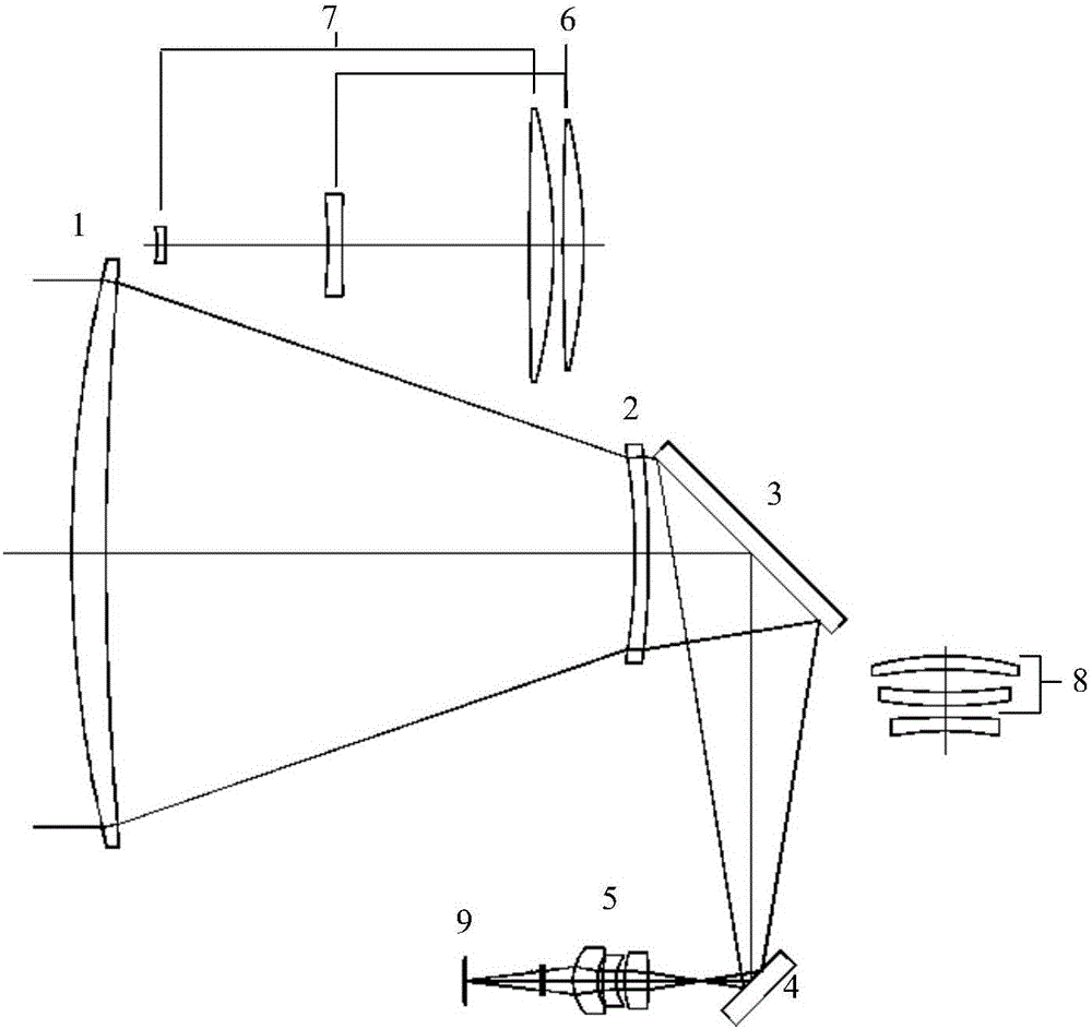
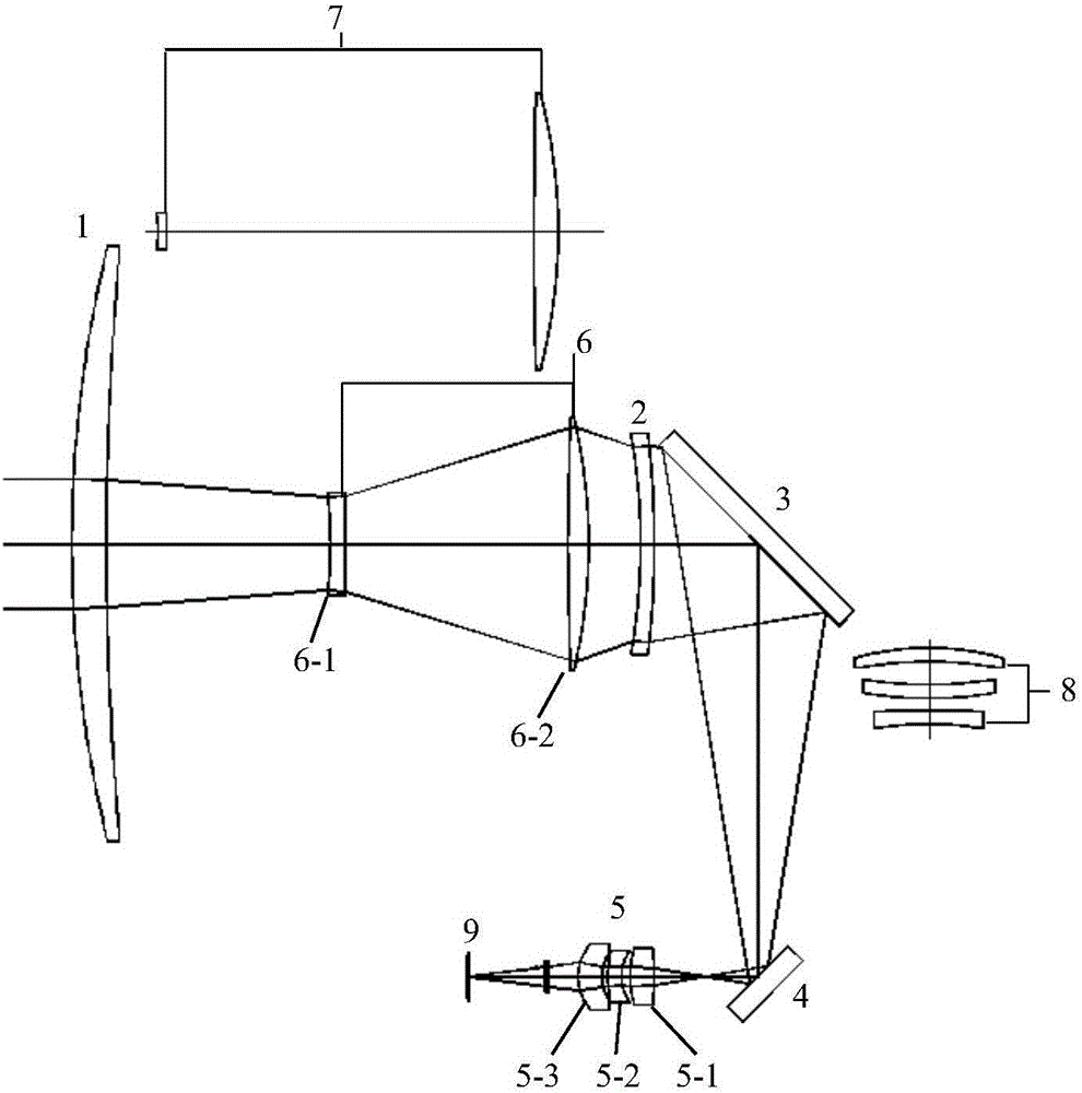
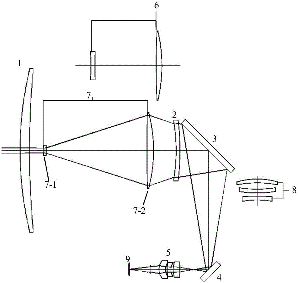
[0034] Figure 1-Figure 4 It is a schematic diagram of the optical path to achieve ultra-small, small, medium and large optical fields of view by cutting into different zoom lens groups.

[0035] The front group objective lens 1, focusing lens group 2, first fixed reflector 3, second fixed reflector 4, converging lens group 5 and detector 9 form a small field of view light path; the motor-driven middle field of view lens group 6 cuts into the small field of view light path The middle field of view light path is formed between the front group objective lens 1 and the focusing lens group 2; the motor drives the middle field of view lens group 6 to cut out the small field of view light path, and at the same time drives the large field of view lens group 7 to cut into the front group objective lens 1 and focus of the small field of view light path The large field of...


PUM


Abstract

The invention relates to a super-long-focal-length infrared multi-view-field light path system, wherein a small-field-of-view light path is formed by a front objective lens set, a focusing lens set, a first fixed reflecting mirror, a second fixed reflecting mirror, a converging lens set and a detector. A motor-driven middle-field-of-view lens set is cut in to be between the front objective lens set and the focusing lens set of the small-field-of-view light path so as to form a middle-field-of-view light path. A motor-driven large-field-of-view lens set is cut in to be between the front objective lens set and the focusing lens set of the small-field-of-view light path so as to form a large-field-of-view light path. A motor-driven super-small-field-of-view lens set is cut in to be between the first fixed reflecting mirror and the second fixed reflecting mirror of the small-field-of-view light path so as to form a super-small-field-of-view light path. According to the technical scheme of the invention, the conversion of multiple infrared fields of view is realized through cutting into different zooming lens sets. Based on the method, the optical axis of each field of view is ensured to be high in precision. Meanwhile, each field of view is ensured to be high in optical transmittance. Moreover, the above field-of-view switching mechanism is simple, high in in-place accuracy and easy to control.

Description

technical field [0001] The invention belongs to infrared optical path technology, and relates to an ultra-long focal length infrared multi-field optical path system. Background technique [0002] For photoelectric detection systems, depending on the requirements, infrared imaging systems usually require small, medium and large fields of view for target recognition, detection, auxiliary navigation and large-scale search functions. [0003] The configurations of infrared multi-field optical systems at home and abroad are mainly double-field and three-field optical systems. Among them, the field of view switching methods are divided into cut-in mode and axial movement mode. The cut-in method realizes the conversion of the field of view by switching between different zoom lens groups. The advantage of this method is that the small field of view has the highest optical axis accuracy and the highest optical transmittance. The disadvantage is that the optical transmittance of the ...

Claims


Application Information

Patent Timeline
Patent Type & Authority Applications(China)
IPC IPC(8): G02B27/00G02B7/04
CPCG02B7/04G02B27/0025G02B27/0081
Inventor 张良兰卫华许泽帅潘晓东
Owner LUOYANG INST OF ELECTRO OPTICAL EQUIP OF AVIC
Why Eureka
Try Eureka