An infrared multi-field optical path system

An optical path system and multi-field of view technology, applied in the field of infrared optics, can solve the problems of low positioning accuracy of the optical axis and field of view, large radial size of the system, complex movement mechanism, etc., and achieve high positioning accuracy, easy control, and high accuracy. Effect of Optical Transmittance

Active Publication Date: 2017-04-19
LUOYANG INST OF ELECTRO OPTICAL EQUIP OF AVIC
View PDF6 Cites 0 Cited by
  • Summary
  • Abstract
  • Description
  • Claims
  • Application Information

AI Technical Summary

Problems solved by technology

[0003] The purpose of the present invention is to provide an infrared multi-field optical path system, which is used to solve the problem of low transmittance, low positioning accuracy between the optical axis and the field of view, or the radial direction of the system. Problems with oversized, complex kinematics and heavy weight

Method used


Image

  • An infrared multi-field optical path system
  • An infrared multi-field optical path system
  • An infrared multi-field optical path system

Examples


Embodiment Construction

[0020] The present invention will be described in further detail below in conjunction with the accompanying drawings.

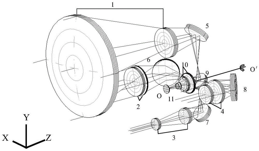
[0021] An infrared multi-field optical path system includes at least two front optical path systems and a rear optical path system, and the rear optical path system includes a rotating mirror group, which is used to form optical paths of different fields of view with each front optical path system and the rear optical path system system.

[0022] Based on the above technical solutions and in conjunction with the accompanying drawings, the following specific implementation is given.

[0023] Such as figure 1 As shown, the front objective lens group 1, the fixed refracting mirror group 5, the rotating mirror group 9, the converging lens group 10 and the detector 11 form a narrow field of view optical path system; based on the narrow field of view optical path, when the motor drives the rotation The mirror group 9 rotates 90° counterclockwise around the rotati...


PUM


Abstract

The invention relates to an infrared multi-view field light path system which comprises at least two front light path systems and a rear light path system. The rear light path system comprises a rotating reflector group, and the front light path systems and the rear light path system respectively form light path systems of different view fields through the rotating reflector group. Infrared multi-view fields are switched by the aid of a method of a rotating reflector, multi-view field light paths are realized by the aid of a rotating reflex reflector, optical view fields are relatively independent, and the optical view fields can simultaneously obtain high optical transmittance. In addition, only the rotating reflex reflector is a movable component, and the rest is fixed components, so that each optical view field can have high optical axis precision. The infrared multi-view field light path system is high in positioning accuracy and easy to control, and a view field switching mechanism is simple.

Description

technical field [0001] The invention relates to an infrared multi-field optical path system, which belongs to the technical field of infrared optics. Background technique [0002] The implementation methods of infrared multi-field zoom optical systems at home and abroad are divided into cut-in method and axial movement method. The cut-in multi-field optical system realizes multi-field conversion by switching between different zoom lens groups. The advantage of this method is that the narrow field of view has the highest optical axis accuracy and the highest optical transmittance. The disadvantage is that the optical transmittance of the large and medium field of view is low, and due to the switching method, the radial size of the system is too large, the movement mechanism is complicated, and the weight is heavy. Axial movement multi-field optical system achieves multi-field conversion through different positions of the zoom lens group and the compensation lens group on the...

Claims


Application Information

Patent Timeline
Patent Type & Authority Patents(China)
IPC IPC(8): G02B26/08
Inventor 张良潘晓东何磊苏朋
Owner LUOYANG INST OF ELECTRO OPTICAL EQUIP OF AVIC
Why Eureka
Try Eureka