Devices and methods for generating beam patterns with controllable intensity, color, or information content

a beam pattern and controllable technology, applied in the field of projected beam patterns, can solve the problems of large power consumption, significant problems, and inability to meet the needs of lighting and heating equipment, and achieve the effect of reducing the uniformity and focus of the beam pattern over large areas and reducing the number of bulbs

Inactive Publication Date: 2010-01-28
OMNILUX
View PDF16 Cites 252 Cited by
  • Summary
  • Abstract
  • Description
  • Claims
  • Application Information

AI Technical Summary

Benefits of technology

[0020]The details of one or more embodiments of these light sources, illumination systems, software, resonant optics, reflectors and / or methods of using them are set forth in the accompanying drawing and in the description below. Other features, objects, and advantages of the invention will become apparent from the description and drawings, and from the claims.

Problems solved by technology

The use of larger power and multiple bulbs is therefore undesirable.
However, significant problems may arise when projecting a light source over a large area.
Additionally, projecting a light source over a wide area using traditional optics may degrade the uniformity and focus of the beam pattern over large areas.

Method used


Image

  • Devices and methods for generating beam patterns with controllable intensity, color, or information content
  • Devices and methods for generating beam patterns with controllable intensity, color, or information content
  • Devices and methods for generating beam patterns with controllable intensity, color, or information content

Examples


Embodiment Construction

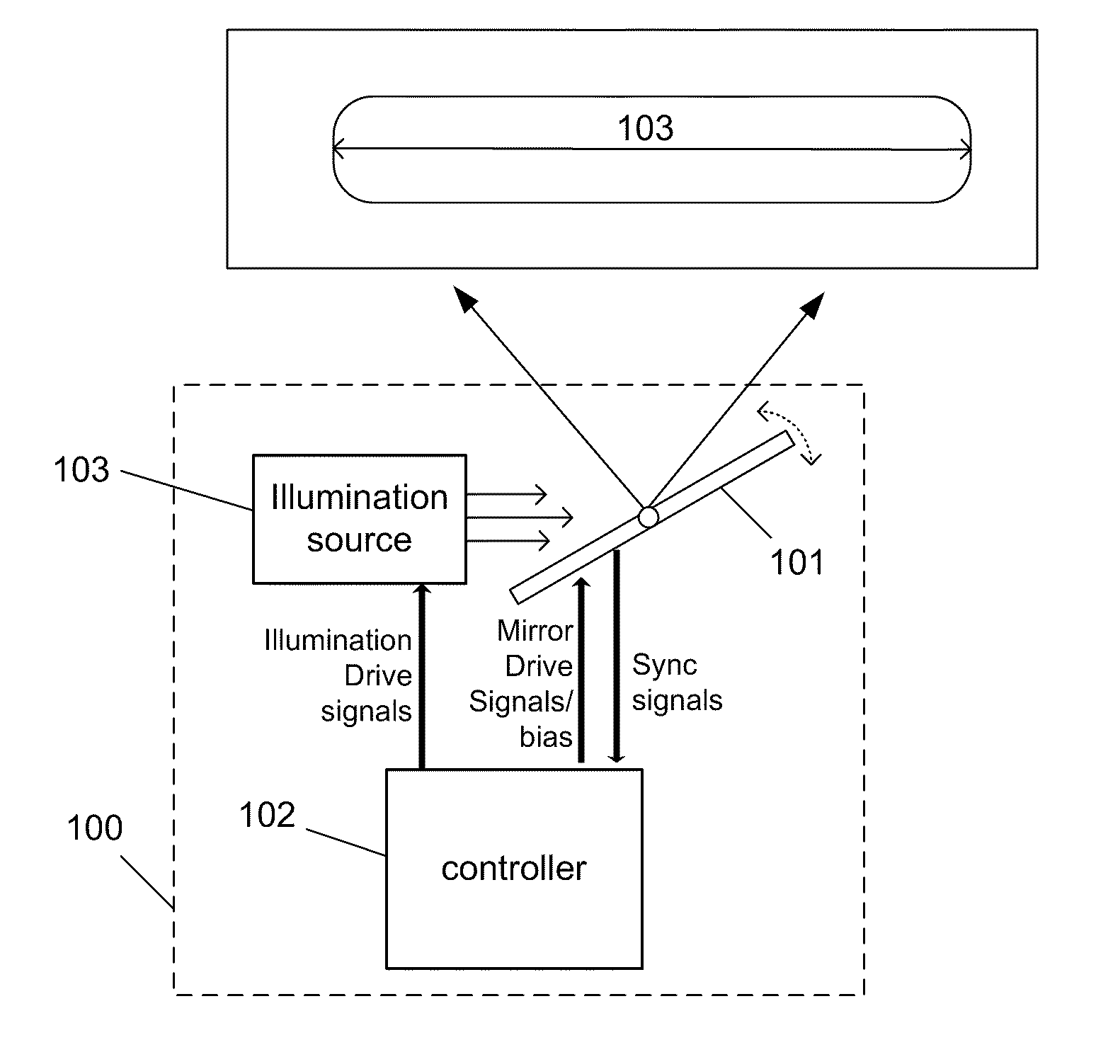
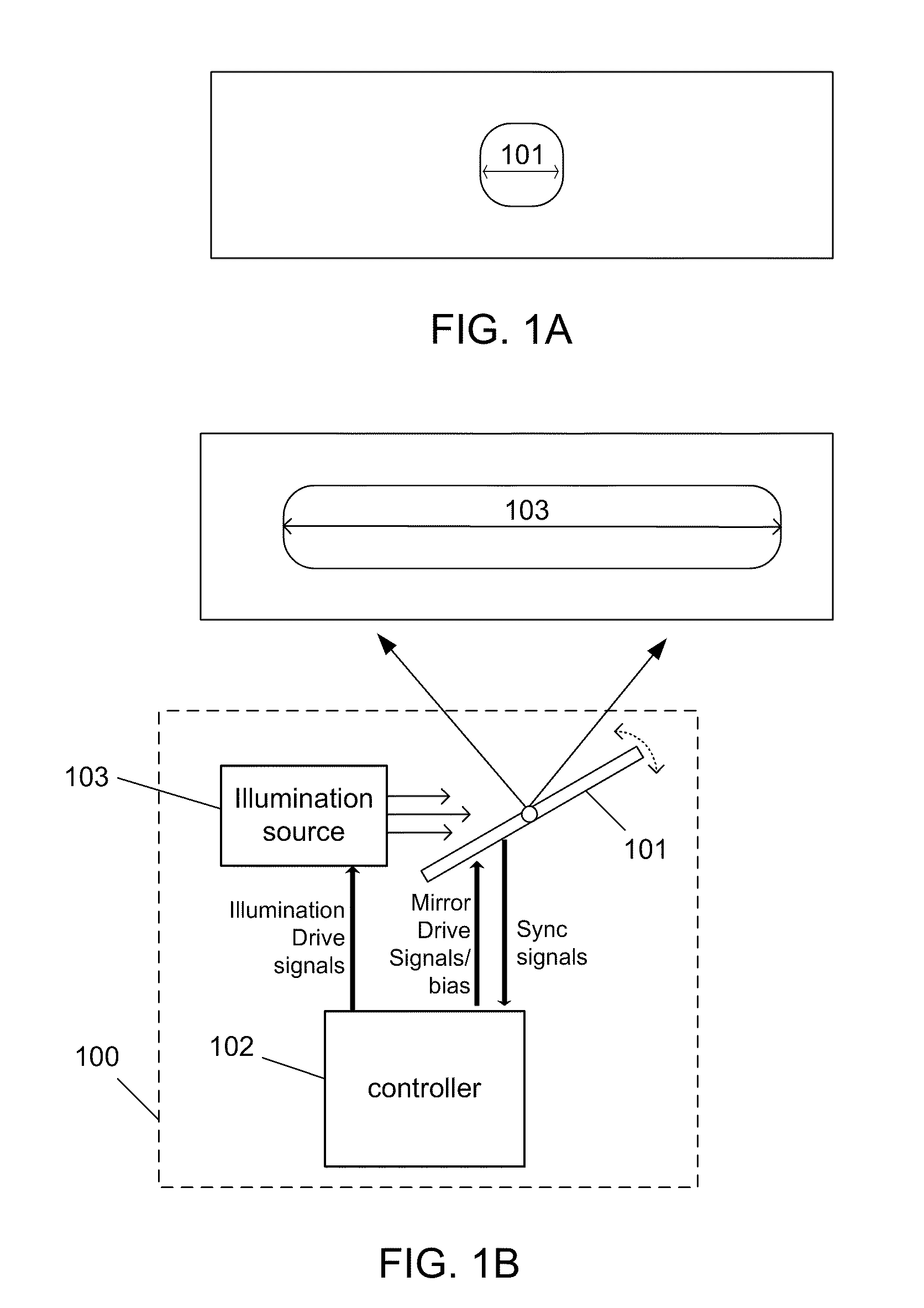
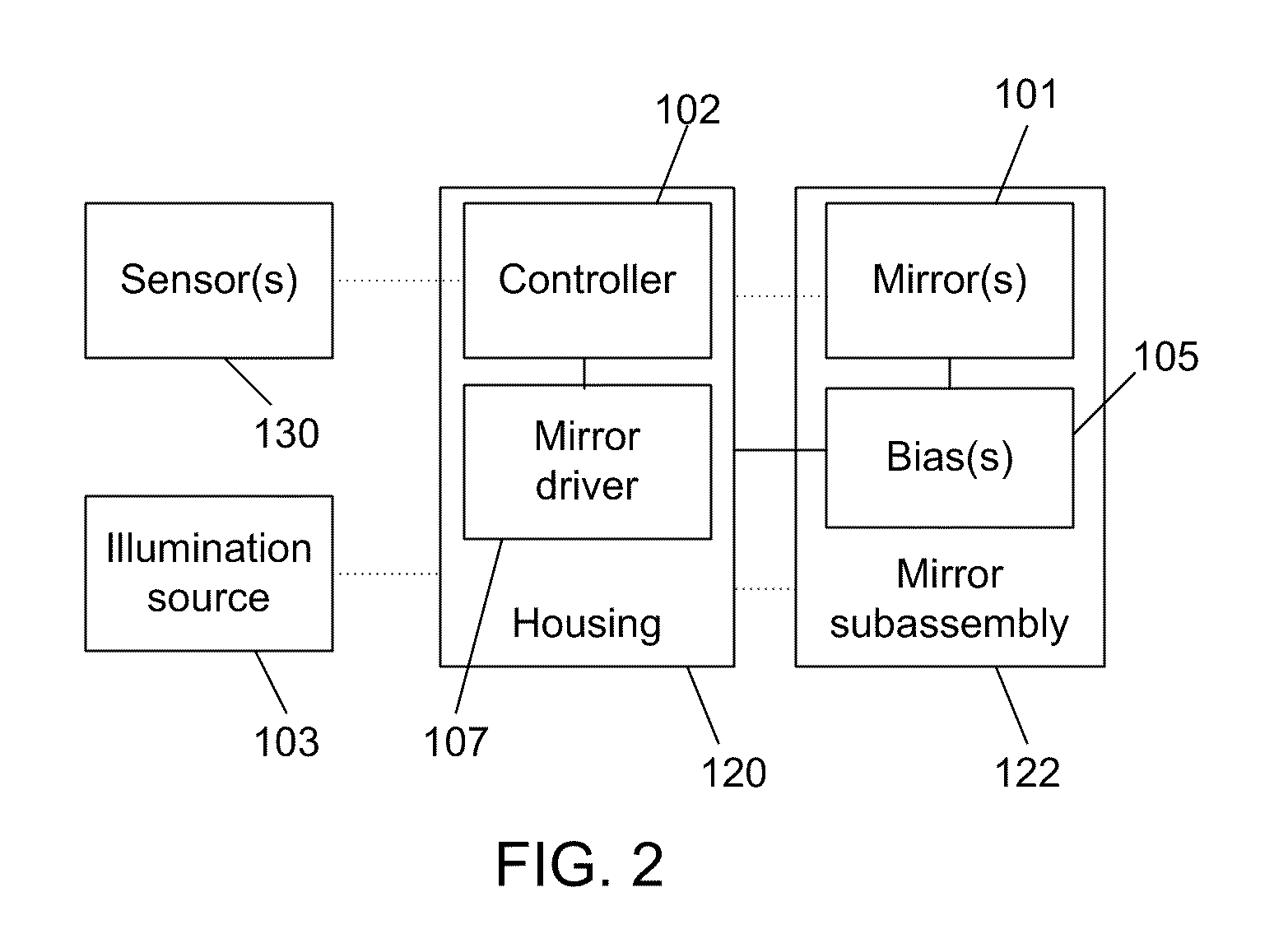
[0057]Described herein are illumination devices, systems and methods for projecting a beam pattern or area of illumination with controllable content. In general, the illumination devices include an illumination source, a mirror (e.g., optic / reflector), and a means of varying a parameter or characteristic of the light source (e.g. color, intensity, etc.). In one example, the illumination source is fixed and modulated over time as the mirror projects a moving beam pattern across a target, thereby forming an illumination pattern. In one example, the mirror moves in a periodic resonant or repetitive fashion, directing the emitted light toward a target or in a desired direction, creating an ability to change the illumination content or characteristic as a function of time. This illumination pattern will typically be interpreted by an observer as illumination of the entire target area, whereby individual time sections may or may not be distinguishable to the observer.

[0058]The following d...


PUM


Abstract

Described herein are systems and methods for controlling an illumination area as a function of time, location, or position. The systems and methods may generate illumination patterns having aesthetic effects or conveying information. In one example, a device for selectively controlling a projected illumination beam pattern of visible or non-visible illumination includes a mirror for receiving and reflecting light from an illumination source, where the mirror is operable to move in an oscillating motion, and a controller for generating time varying signals for causing the illumination source to vary a characteristic of the light (e.g., color, intensity, shape, or combinations thereof) from the illumination source and produce a predetermined illumination pattern. The controller (which may include suitable logic such as software, firmware, hardware, or combinations thereof) may operate to modulate a characteristic of the illumination source over time based on the orientation of the mirror and the predetermined illumination pattern.

Description

RELATED APPLICATIONS[0001]This application claim benefit to previously filed U.S. provisional patent application Ser. No. 61 / 028,460 entitled “DEVICES AND METHODS FOR GENERATING BEAM PATTERNS WITH CONTROLLABLE INTENSITY, COLOR, OR INFORMATION CONTENT,” filed on Feb. 13, 2008, which is incorporated herein by reference in its entirety for all purposes. This application is further related to previously filed U.S. patent application Ser. No. 11 / 665,109, entitled “DEVICES AND METHODS FOR EFFICIENT RESONANT,” filed on Apr. 10, 2007, and U.S. provisional patent application Ser. No. 60 / 922,711, entitled “METHOD FOR CONTROL OVER MECHANICAL RESONANT SYSTEM,” filed on Apr. 4, 2007, both of which are incorporated herein by reference in their entirety as if fully set forth herein.BACKGROUND[0002]1. Field:[0003]This application generally relates to the field of illumination devices including, white, color, and non-visible illumination. In particular, the application relates to a projected beam pa...

Claims


Application Information

Patent Timeline
Patent Type & Authority Applications(United States)
IPC IPC(8): H05B41/36F21S8/00
CPCF21S10/02F21Y2101/02H05B33/0872H05B33/0803H05B33/0857F21Y2101/025F21Y2115/30F21Y2115/10H05B45/20H05B47/165H05B45/00
Inventor GUTIERREZ, JR., ENRIQUE
Owner OMNILUX
Why Eureka
Try Eureka